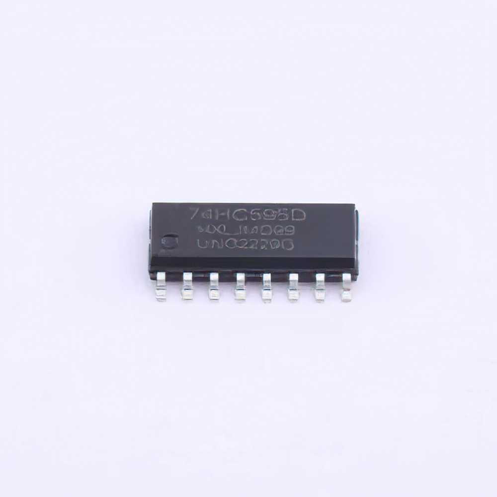
This article explores common issues encountered with the 74HC595D shift register, offering effective troubleshooting techniques and solutions to help engineers and hobbyists optimize their projects. Learn how to diagnose issues such as improper connections, Power failures, signal integrity problems, and more.
74HC595 D, shift register, troubleshooting, electronics, common issues, solutions, serial to parallel, GPIO, microcontroller, Arduino, circuit design, power supply, data transmission
Understanding the 74HC595D Shift Register and Common Troubleshooting Problems
The 74HC595D is a popular 8-bit serial-in, parallel-out shift register that allows users to control multiple outputs using fewer pins on a microcontroller. It’s commonly used in a variety of electronic projects, such as controlling LED s, motors, and displays. While the device is relatively easy to use, there are certain issues that users may encounter during setup or operation. This article outlines the common problems with the 74HC595D and provides troubleshooting tips to solve them efficiently.
Overview of the 74HC595D
Before delving into the troubleshooting steps, it’s crucial to understand the key functions of the 74HC595D. The shift register operates on the principle of serial communication, where data is shifted bit by bit through the IC and presented on the parallel output pins. This reduces the number of pins required to control multiple devices, making it ideal for use in applications like Arduino projects and other microcontroller-based systems.
The 74HC595D has the following key pins:
DS (Data Serial Input): Receives the serial data.
SH_CP (Shift Clock Pin): Shifts the data on the rising edge of the clock signal.
ST_CP (Storage Clock Pin): Transfers the shifted data to the output register.
Q0-Q7 (Parallel Output Pins): The 8 output pins that provide the shifted data.
OE (Output Enable): Controls whether the outputs are active or in high-impedance state.
With this basic understanding, let’s explore common problems that can arise during the setup and operation of the 74HC595D.
1. Power Supply Issues
One of the most common problems when working with the 74HC595D is inadequate power supply or improper voltage levels. The device operates on a supply voltage range of 2V to 6V, but using a voltage outside this range may result in malfunction or failure of the IC.
Symptoms of Power Supply Issues:
No response from the output pins.
Unreliable or intermittent behavior.
Incorrect data output, such as random values or frozen states.
Troubleshooting Power Supply Issues:
Check the Voltage: Use a multimeter to verify that the voltage at the Vcc and GND pins of the 74HC595D falls within the acceptable range (typically 5V for most applications).
Current Capacity: Ensure that the power supply can provide sufficient current for both the shift register and any connected devices (e.g., LED s or displays). Insufficient current may cause erratic behavior.
Decoupling capacitor s: Place a 0.1µF ceramic capacitor near the power pins of the shift register to filter any noise or transients in the power supply.
2. Incorrect Wiring and Connections
Another common issue arises from incorrect connections between the 74HC595D and other components. Miswiring, especially with the data and clock pins, can lead to erratic behavior or failure to transmit data correctly.
Symptoms of Incorrect Wiring:
Outputs stay high or low, regardless of input data.
Data is not properly shifted or output pins don’t reflect expected values.
Constant or undefined states on the output pins.
Troubleshooting Wiring Issues:
Double-Check Pin Connections: Carefully verify the connections to the serial data input (DS), shift clock (SHCP), and storage clock (STCP) pins. Ensure that these pins are connected to the correct pins on the microcontroller or Arduino board.
Use Breadboards or Socket s: When prototyping, use breadboards or IC sockets to easily swap out the 74HC595D and check if the issue is related to the IC itself.
Secure Connections: Loose connections can often be the root cause of intermittent issues. Ensure all wires are firmly connected and avoid using long, thin wires that may introduce signal noise.
3. Timing and Clock Synchronization
The 74HC595D requires proper synchronization of the shift clock (SHCP) and storage clock (STCP) to function correctly. Misconfigured clock signals can lead to incorrect data being shifted or stored.
Symptoms of Clock Issues:
Data appears scrambled or out of order.
The shift register does not respond to clock signals.
Unpredictable or delayed outputs.
Troubleshooting Clock Issues:
Check Clock Timing: Ensure that the shift clock (SHCP) and storage clock (STCP) are properly synchronized. The shift clock controls when the data is shifted, while the storage clock determines when the shifted data is moved to the output pins.
Use Appropriate Clock Frequencies: The 74HC595D can operate at relatively high clock frequencies. However, if the clock signal is too fast for the microcontroller to process, data may be shifted incorrectly. Lower the clock frequency if necessary.
Monitor Clock Signals: Use an oscilloscope to check the waveform of the shift and storage clock signals. If the waveforms look incorrect, adjust the clock source or check for timing issues in the microcontroller code.
4. Data Transmission Errors
Data transmission errors can occur if the data is not correctly shifted into the 74HC595D or if there is noise on the data line. This can lead to incorrect output or failure to update the output pins.
Symptoms of Data Transmission Errors:
The output pins don’t reflect the expected data values.
Data is shifted incorrectly or skipped.
The output pins don’t change even when new data is sent.
Troubleshooting Data Transmission Issues:
Check Data Integrity: Ensure that the serial data (DS) pin is properly receiving clean data from the microcontroller. Use a logic analyzer to monitor the data stream and verify that it matches the expected values.
Signal Integrity: Use short, shielded wires for the data and clock lines to minimize noise and signal degradation, especially in longer connections or high-speed applications.
Verify Shift Register Initialization: The 74HC595D requires a proper initialization sequence. Ensure that the shift register is properly reset and that data is being shifted into it correctly.
Advanced Troubleshooting and Solutions for the 74HC595D
Now that we have covered the basic troubleshooting steps, let's dive into some more advanced techniques to ensure that your 74HC595D shift register works reliably in all scenarios. Whether you are working with complex circuits or troubleshooting persistent issues, these tips will help you get the most out of this versatile component.
5. Troubleshooting with Multiple Shift Registers
In some applications, multiple 74HC595D shift registers are daisy-chained together to control a large number of outputs. While this is an effective way to extend the number of control pins, it can also introduce new challenges.
Symptoms of Multiple Shift Register Issues:
Only the first shift register in the chain is working correctly.
Output pins do not reflect the expected data on subsequent shift registers.
Data is not correctly passed between shift registers.
Troubleshooting Multiple Shift Register Connections:
Verify Daisy-Chaining: Check that the QH’ (serial output) pin of the first shift register is properly connected to the DS (serial input) pin of the next shift register. Ensure the connection is secure and the data flow is uninterrupted.
Monitor Data Flow: Use a logic analyzer to track the data as it passes through the chain of shift registers. This can help identify where the data flow is breaking down.
Timing Adjustments: If you are experiencing delays or missed data, adjusting the timing of the clock signals may help. Ensure that the clock is fast enough for data to propagate through all the shift registers but not so fast that it overwhelms the system.
6. Output Pin Behavior and LED Control
When using the 74HC595D to control LEDs or other outputs, there are some specific issues you may encounter related to the state of the output pins.
Symptoms of Output Pin Problems:
LEDs remain off or on regardless of input data.
Inconsistent behavior in the LEDs, with some turning on while others stay off.
High current draw or overheating of the IC.
Troubleshooting Output Pin Issues:
Check Output Enable (OE) Pin: The OE pin controls whether the output is enabled or in a high-impedance state. If this pin is tied low, outputs will be active. If it is tied high, the outputs will be in a high-impedance state. Ensure that the OE pin is properly controlled in your circuit.
Current Limiting for LEDs: If you are driving LEDs directly from the output pins, ensure that each LED is paired with an appropriate current-limiting resistor to prevent excessive current draw that could damage the IC or the LEDs themselves.
Output Drive Capability: The 74HC595D can only source or sink a limited amount of current (typically 6-8 mA per pin). If you are driving power-hungry devices like motors or large displays, consider using external transistor s or MOSFETs to handle the higher current demands.
7. Software and Programming Errors
In many cases, the issue may not lie with the hardware but with the software controlling the shift register. Incorrect timing, improper data formatting, or failure to properly manage the shift registers can lead to malfunctioning behavior.
Symptoms of Software Issues:
The shift register does not update even when new data is sent.
The output pins do not reflect the expected values, even when the correct data is provided.
Timing inconsistencies lead to unpredictable results.
Troubleshooting Software Errors:
Check Code for Initialization: Ensure that the 74HC595D is properly initialized in the software before attempting to send data. This includes setting up the clock and data pins, as well as ensuring that the shift register is correctly reset.
Data Formatting: Ensure that data is formatted correctly before being shifted into the register. For instance, the data must be sent in the correct bit order, and the number of bits should match the size of the shift register (8 bits per IC).
Timing Adjustments: If using an Arduino or similar microcontroller, make sure that the timing between clock pulses is sufficient for the shift register to process data. If the timing is too fast, some bits may be missed or corrupted.
Conclusion
The 74HC595D is a powerful and versatile shift register that simplifies the process of controlling multiple outputs with minimal wiring. However, like any electronic component, it can encounter issues during setup or operation. By understanding the common problems and troubleshooting them systematically, you can ensure that your 74HC595D projects function smoothly and reliably. Whether you're working with power supply issues, wiring problems, or software bugs, following the right steps will help you resolve problems quickly and keep your projects on track.
Incorporate these troubleshooting techniques into your workflow to enhance your electronics projects and build more robust, reliable systems!
Partnering with an electronic components supplier sets your team up for success, ensuring the design, production, and procurement processes are quality and error-free.


