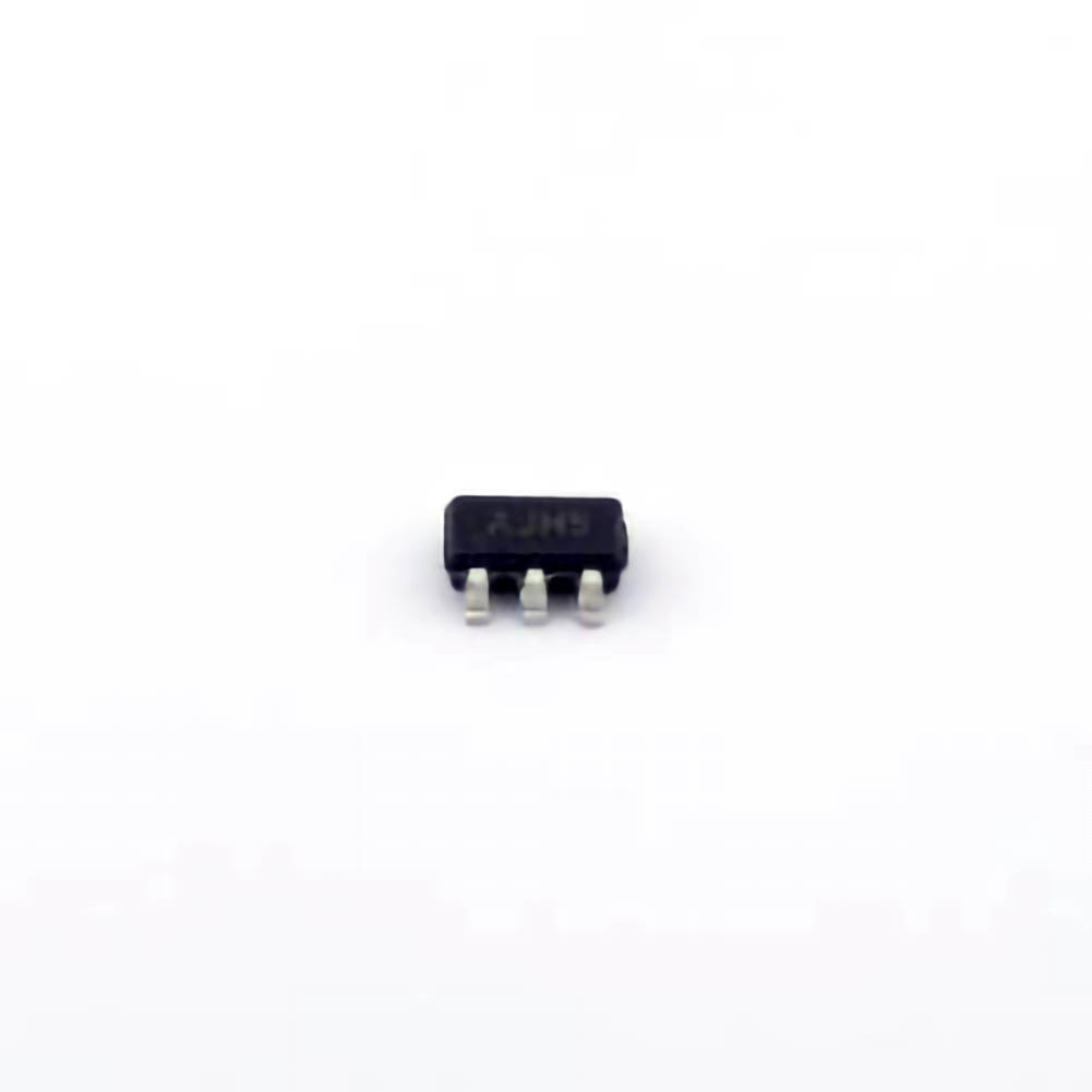
The MCP4725 A0T-E/CH is a high-performance Digital-to-Analog Converter (DAC) often used in embedded systems, IoT devices, and other applications requiring precise analog signals. However, like all advanced components, it can encounter issues during implementation. This article delves into the common problems engineers face when working with the MCP4725A0T-E/CH and offers practical troubleshooting solutions to help keep projects on track.
MCP4725A0T-E/CH, Digital-to-Analog Converter, DAC, troubleshooting, engineering solutions, embedded systems, I2C Communication , signal integrity, device calibration
Understanding the MCP4725A0T-E/CH DAC and Common Issues
The MCP4725A0T-E/CH is a versatile and compact Digital-to-Analog Converter (DAC) produced by Microchip Technology. It provides 12-bit resolution and is controlled via I2C communication, making it ideal for embedded systems where space and Power efficiency are critical. However, its high precision and I2C interfacing can sometimes cause confusion during integration, particularly for those new to working with DACs or I2C protocol.
Key Features of the MCP4725A0T-E/CH:
12-bit resolution – This provides a high degree of accuracy in generating analog signals from digital input.
I2C interface – The device can be controlled using the popular I2C communication protocol, which simplifies the wiring and reduces the number of required GPIO pins.
Low power consumption – This makes it ideal for battery-operated or low-power devices.
Internal EEPROM – The device supports storing a user-defined DAC output value, which can be restored on power-up.
Fast output update – The DAC can quickly convert a digital value into an analog signal with minimal delay.
Despite these advantages, several common issues may arise during its use. Below, we will address some frequent problems and provide troubleshooting strategies.
1. I2C Communication Issues
Since the MCP4725A0T-E/CH is controlled via I2C, communication problems are one of the most common challenges engineers encounter. These issues can stem from several sources:
Incorrect I2C Address: The MCP4725A0T-E/CH has a default I2C address of 0x60, but this can be modified depending on the configuration of the ADDR0 pin. If you're having trouble communicating with the device, it’s worth verifying that you are using the correct address.
Bus Congestion or Clock Issues: I2C operates on a shared bus, and if other devices are also using I2C or if the clock speed is too high, it may result in communication failures. Ensure that the I2C bus is not overloaded, and that the SCL (clock) and SDA (data) lines are functioning properly. A good practice is to use an oscilloscope or logic analyzer to monitor the signal integrity on these lines.
Pull-up Resistors : I2C requires proper pull-up resistors on the SDA and SCL lines. Insufficient pull-ups or faulty resistors can cause unreliable communication or a failure to detect the MCP4725A0T-E/CH device on the bus. Check that appropriate resistors (typically 4.7kΩ to 10kΩ) are in place.
2. Power Supply and Grounding Problems
The MCP4725A0T-E/CH, like all digital components, requires stable power and proper grounding. Voltage fluctuations, poor grounding, or incorrect power supply voltages can cause erratic behavior or complete failure.
Voltage Supply: Ensure that the device is powered within the recommended voltage range (2.7V to 5.5V). If the voltage is too high or too low, the device may not function properly or may be damaged.
Decoupling capacitor s: Place a 0.1µF ceramic capacitor close to the power and ground pins to filter out any high-frequency noise. This improves the overall stability and performance of the DAC.
Grounding Issues: A common mistake in embedded systems is poor grounding, which can introduce noise and lead to incorrect signal outputs. Make sure the ground of the MCP4725A0T-E/CH is solidly connected to the ground of the microcontroller or power supply, and that no ground loops exist.
3. Signal Integrity and Output Issues
After ensuring that communication and power are stable, the next set of issues often relates to the analog output of the MCP4725A0T-E/CH.
Output Range and Scaling: The MCP4725A0T-E/CH has a 12-bit resolution, meaning it can produce a range of 0 to 4095 (in digital terms). However, you may encounter issues with the output scaling. For example, if you’re using a 3.3V supply and you expect the DAC to output between 0V and 3.3V, you should ensure that your code and calculations match this expectation.
Noise on the Output: If you observe noise on the output signal, it could be due to electromagnetic interference ( EMI ) or issues with the power supply or grounding. Using low-pass filtering on the DAC output or placing the device on a PCB with proper grounding and shielding can reduce this noise.
4. EEPROM and Non-Volatile Storage Issues
The MCP4725A0T-E/CH features internal EEPROM, allowing you to store the DAC output value for recovery after power cycles. However, improper use or programming of the EEPROM can lead to issues.
Corrupted EEPROM: If you store an incorrect value in EEPROM, or if you attempt to write to the EEPROM too frequently, it may cause corruption. Make sure that the EEPROM write operations are executed correctly and within the recommended write cycles (typically about 100,000 cycles).
EEPROM Load Timing : When the device powers up, the EEPROM-loaded DAC value is applied to the output. If you encounter delayed or incorrect outputs, verify that the EEPROM has been programmed correctly and that the timing of the load operation is as expected.
Advanced Troubleshooting Solutions for the MCP4725A0T-E/CH
In this section, we will discuss more advanced troubleshooting techniques and solutions to ensure the smooth operation of the MCP4725A0T-E/CH in your application.
5. Understanding DAC Resolution and Accuracy
The MCP4725A0T-E/CH offers 12-bit resolution, which provides a theoretical accuracy of approximately 0.8mV (in a 3.3V system). However, practical issues such as power supply noise, grounding errors, and poor calibration can affect the accuracy of the output.
Calibration Issues: Ensure that the device is properly calibrated before use. Microchip provides application notes and example code for calibrating DACs, and using them ensures the output is accurate. If you notice discrepancies in the output, re-check the calibration settings.
Temperature Effects: The accuracy of DACs can vary with temperature. If your application operates in a temperature-sensitive environment, take temperature drift into consideration. You might need to implement temperature compensation in your system or choose a DAC with better temperature stability if necessary.
6. Optimizing Code and Timing
Incorrect timing or inefficient code can also cause problems, especially when it comes to writing values to the MCP4725A0T-E/CH over I2C.
I2C Timing Delays: When sending commands or data to the MCP4725A0T-E/CH, ensure that your I2C timings are within the specifications in the datasheet. An incorrect delay between writes or reads can result in failed communication or miscommunication with the device.
Use of I2C Transaction Buffers : Some microcontrollers may require the use of buffers to handle I2C transactions more efficiently. This is especially true for devices that need multiple bytes to be transmitted in a single operation, such as the MCP4725A0T-E/CH. Check the I2C transaction handling capabilities of your microcontroller to avoid data corruption.
7. Test the DAC in Isolation
If you continue to encounter issues, consider isolating the DAC from other components in your system to rule out interactions that may be causing problems. By testing the MCP4725A0T-E/CH in a minimal environment (e.g., directly connected to a microcontroller with only power, ground, SDA, and SCL), you can confirm that the DAC itself is functioning correctly.
Testing with Known Good Code: Use a known, working I2C library and example code to communicate with the DAC. This helps ensure that the issue is not related to software bugs or timing problems in your custom code.
8. Consult Documentation and Manufacturer Support
If all else fails, consult the datasheet and application notes from Microchip, as they provide extensive details on troubleshooting specific issues. Additionally, Microchip offers technical support that can provide guidance for more complex issues.
In conclusion, troubleshooting the MCP4725A0T-E/CH requires a systematic approach. Start by verifying the communication interface (I2C), followed by checking power, grounding, and signal integrity. Calibration and EEPROM settings also play a key role in ensuring optimal performance. With careful attention to detail and an understanding of potential issues, engineers can successfully integrate and troubleshoot the MCP4725A0T-E/CH in a wide range of applications.
Partnering with an electronic components supplier sets your team up for success, ensuring the design, production, and procurement processes are quality and error-free.


