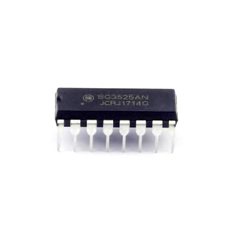
Understanding the SG3525ANG and Common Issues
The SG3525AN G is a popular integrated circuit (IC) primarily used as a pulse width modulation (PWM) controller in Power supplies. It’s widely employed in DC-DC converters, inverters, switching power supplies, and various other power Management applications. This IC is favored for its ease of use, versatility, and ability to generate stable PWM signals for controlling switching transistor s like MOSFETs or IGBTs.
Despite its popularity and reliable performance, like any electronic component, the SG3525ANG can run into problems during operation. Troubleshooting these issues requires a good understanding of the IC’s internal structure, external components, and the overall circuit in which it operates.
In this article, we will explore common troubleshooting issues encountered with the SG3525ANG and discuss effective solutions to get your power supply circuits back on track.
Overview of the SG3525ANG IC
Before diving into troubleshooting, let’s understand the SG3525ANG’s basic functionality. It features several key attributes that make it suitable for power supply applications:
Oscillator Circuit: The SG3525ANG contains an internal oscillator that sets the frequency of the PWM signal. The oscillator is externally adjustable via a resistor and capacitor network, allowing users to customize the switching frequency.
PWM Control: The IC generates a PWM signal that modulates the duty cycle (on-time vs off-time) to control the output voltage. This duty cycle adjustment helps maintain voltage regulation in the power supply.
Error Amplifier: The SG3525ANG includes an error amplifier that compares the feedback voltage from the output with a reference voltage to maintain stable operation.
Driver Outputs: The IC has two outputs, typically used to drive the gates of switching transistors like MOSFETs or IGBTs. These transistors control the flow of current through the transformer or load in the power supply.
Protection Features: Built-in protection features, such as over-current protection and under-voltage lockout, ensure that the circuit remains safe during operation.
While the SG3525ANG is relatively robust, several common issues may arise during its use. These issues can range from minor glitches to complete failure of the power supply. Below are some of the typical problems and their root causes.
1. No Output or Low Output Voltage
One of the most common problems encountered with the SG3525ANG is no output or low output voltage from the power supply. This issue can be traced back to several possible causes:
Faulty Oscillator: If the oscillator circuit fails to oscillate, the PWM signal will not be generated, and the power supply will output no voltage. Check the Timing components ( Resistors and Capacitors connected to pins 5, 6, and 7) for any defects or incorrect values.
Incorrect Feedback: The feedback voltage from the output to the error amplifier might be missing or improperly configured. This can cause the PWM signal to not be modulated correctly, leading to low or zero output voltage. Ensure that the feedback loop is properly connected and that the feedback voltage is within the expected range.
Faulty Output Drivers : The SG3525ANG has two output drivers (pins 11 and 14) that control the switching devices. If one of the drivers is damaged or not functioning, the power supply will not switch properly, resulting in a low or zero output. Check for any short circuits or component failures in the driver stage.
Broken Power Supply to the IC: If the IC is not receiving the required supply voltage (pins 8 and 11), it won’t function. Ensure that the power supply is stable and within the required voltage range for the SG3525ANG.
2. High Ripple or Noise on the Output
Another common problem with power supplies using the SG3525ANG is high ripple or noise on the output voltage. This can lead to instability in sensitive circuits and affect the performance of the power supply. Possible causes include:
Improper Filtering: High ripple or noise often results from inadequate filtering of the PWM signal. Make sure that proper decoupling capacitors are placed near the input and output of the IC, and that the power supply has sufficient bulk capacitors to smooth out the DC voltage.
Inadequate Grounding: Poor grounding can introduce noise into the system, which then reflects as ripple on the output voltage. Ensure that the ground planes are solid, and the ground connections are low impedance.
PCB Layout Issues: A poor PCB layout can cause parasitic inductances and capacitances that result in high-frequency noise. Ensure that the switching nodes are kept short, and that there is a proper separation between high and low-current paths to prevent noise coupling.
3. Overheating of the SG3525ANG
Overheating is another issue that can occur, especially when the SG3525ANG is driving high-power devices. If the IC gets too hot, it can fail or cause instability in the power supply. Common reasons for overheating include:
Excessive Load: If the power supply is driving too much current or has a short circuit at the output, the SG3525ANG might overheat. Check the load conditions and ensure that the output is within the rated current limits.
Improper Heat Dissipation: If the SG3525ANG is housed in a package with poor heat dissipation, it may overheat. Ensure that the IC is mounted on a PCB with adequate thermal vias or heat sinks.
Incorrect Switching Frequency: Running the SG3525ANG at a very high frequency can lead to increased power dissipation. Ensure that the oscillator is set to an appropriate frequency for the application, typically in the range of 20-100 kHz for most power supply designs.
4. Excessive Current Draw
Another issue that can occur is excessive current draw from the power supply, which can stress the SG3525ANG and other components in the circuit. This is often caused by:
Faulty Switching Transistors: If the switching transistors (MOSFETs or IGBTs) are shorted or damaged, the power supply can draw excessive current. Test the switching devices to ensure they are operating correctly.
Short Circuits in the Power Supply: A short circuit at the output or within the circuit can cause the IC to draw excessive current. Check for any solder bridges or damaged components that could be causing a short.
Conclusion
The SG3525ANG is a highly reliable and widely used PWM controller in power supply applications, but like all electronic components, it can encounter various issues. Troubleshooting these issues requires an understanding of the IC’s internal circuitry, the external components, and the overall power supply design. In Part 2, we will dive deeper into specific diagnostic techniques, repair methods, and preventive measures to ensure the long-term reliability of power supply circuits using the SG3525ANG.
Advanced Troubleshooting Techniques and Solutions for SG3525ANG
In Part 1, we discussed common issues such as no output, high ripple, overheating, and excessive current draw when using the SG3525ANG PWM controller. Now, let's explore advanced troubleshooting techniques, practical solutions, and preventive measures to ensure optimal operation of your SG3525ANG-based power supply circuits.
1. Using an Oscilloscope for Troubleshooting
An oscilloscope is an invaluable tool when diagnosing issues with the SG3525ANG or any PWM controller circuit. Here’s how you can use it effectively:
Check the Oscillator Signal: First, verify that the SG3525ANG's internal oscillator is working properly. You should see a periodic waveform at pins 5, 6, or 7 (the timing capacitor). If there is no signal or the waveform is distorted, the oscillator might be faulty or misconfigured. Check the timing resistor and capacitor values.
PWM Waveform: Use the oscilloscope to observe the PWM waveform at the output pins (11 and 14). A clean square wave indicates that the IC is functioning properly, while a distorted or absent signal suggests problems with the output drivers or the control loop.
Feedback Signal: Inspect the feedback voltage coming from the output and entering the error amplifier (pin 1). If this voltage is not within the expected range, the IC might not be properly regulating the output. Ensure that the feedback loop components (resistors and capacitors) are correct.
Driver Outputs: If the output pins are not switching properly, check for issues in the driver stage. Look for irregularities in the gate signal that could indicate a problem with the MOSFET gate drivers.
2. Component Replacement
If specific components in the SG3525ANG circuit are identified as faulty, replacing them is often the best solution. Here are some common component failures and how to address them:
Timing Capacitors and Resistors: These components determine the switching frequency and duty cycle of the PWM signal. If the frequency is incorrect, replace these components with the correct values specified in the design.
Feedback Network: If the feedback resistors or capacitors are damaged or incorrectly rated, it can lead to improper regulation. Replace the faulty components with the correct values.
Output Transistors: If the switching MOSFETs or IGBTs are damaged, replace them with the same type and rating. Be sure to check for any other issues that could have caused the failure, such as excessive current or overheating.
3. Preventive Measures
To avoid future issues with your SG3525ANG-based circuits, consider the following preventive measures:
Use Proper Decoupling Capacitors: Ensure that appropriate decoupling capacitors are placed near the IC to filter out high-frequency noise and stabilize the power supply.
Good PCB Layout Practices: A good PCB layout is essential for minimizing noise and improving overall circuit performance. Keep high-current paths short, provide solid ground planes, and use adequate trace widths for power handling.
Heat Management: Ensure that the SG3525ANG and other critical components have proper heat dissipation. Use heatsinks, thermal vias, or other cooling methods as needed to prevent overheating.
Component Ratings: Always use components with the correct voltage and current ratings to ensure reliable operation. Underrated components are more prone to failure under stress.
Conclusion
Troubleshooting the SG3525ANG PWM controller requires a methodical approach, starting with understanding its basic functionality and moving towards detailed diagnostic techniques. By using tools like oscilloscopes, performing component replacements, and adhering to preventive measures, you can ensure that your power supply circuits operate reliably and efficiently. With the knowledge gained in this article, you can confidently tackle any issues related to the SG3525ANG and maintain your power supply systems in top condition for years to come.
If you're looking for models of common electronic components or more information about ( Electronic Components Product Catalog ) datasheets, compile all your purchasing and CAD information into one place.Partnering with an electronic components supplier sets your team up for success, ensuring the design, production, and procurement processes are quality and error-free. Contact us for free today.

