Sure, I can write the article for you! Here’s the first part of the soft article on “ TMS320F28034PNT Common Troubleshooting and Solutions.” Since you requested two parts, I will divide the content as you specified.
This article provides an in-depth guide on common troubleshooting issues and practical solutions for the TMS320F28034PNT microcontroller. Whether you're a beginner or an experienced engineer, this resource will help you diagnose and resolve issues efficiently, ensuring smoother development and improved system performance.
TMS320F28034PNT troubleshooting, Texas Instruments microcontroller, troubleshooting solutions, microcontroller debugging, embedded systems, TMS320F28034 issues, C2000 series troubleshooting
Identifying and Diagnosing Common Issues in TMS320F28034PNT
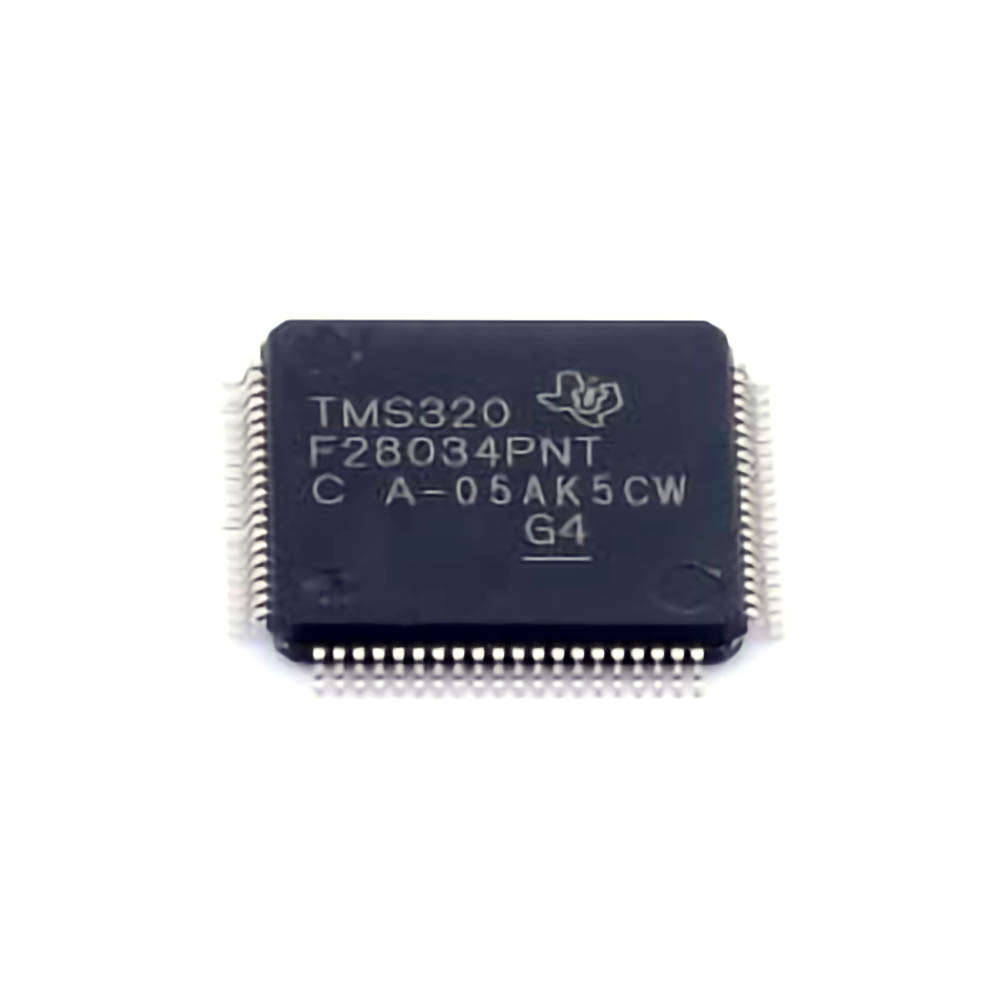
The TMS320F28034PNT is a Power ful and widely used microcontroller from Texas Instruments, part of the C2000 series. It is designed for high-performance applications in areas such as motor control, power management, and digital signal processing. However, like any sophisticated microcontroller, users may encounter issues during development and implementation. This article outlines common troubleshooting problems and offers practical solutions for resolving them.
1. Power Supply Issues: The Foundation of Stability
A reliable power supply is crucial for the proper functioning of any microcontroller, including the TMS320F28034PNT. Inadequate or fluctuating voltage levels can lead to erratic behavior, resets, or complete failure of the microcontroller. Here are the most common power-related issues:
Problem: Power Supply Instability
Symptoms: The device resets intermittently, behaves unpredictably, or fails to start up.
Diagnosis: Check the power supply voltage using an oscilloscope. Ensure that the supply voltage is stable and within the recommended range (typically 3.3V for the TMS320F28034PNT). Fluctuations, noise, or dips in voltage can cause the microcontroller to malfunction.
Solution: Use a regulated power supply with low ripple and noise. Consider adding decoupling capacitor s close to the microcontroller’s power pins to filter out high-frequency noise.
Problem: Brown-Out Reset
Symptoms: The device continuously resets or fails to start due to low voltage.
Diagnosis: Check the brown-out reset (BOR) feature of the microcontroller. The TMS320F28034PNT has an integrated BOR circuit that will trigger a reset if the voltage falls below a certain threshold.
Solution: Adjust the BOR threshold in the software settings, or provide a more stable and sufficient power source.
2. Incorrect Clock Configuration: Timing is Everything
Clock configuration issues can cause a variety of problems, including system slowdowns, Communication failures, or even complete failure to boot. The TMS320F28034PNT uses an external crystal oscillator or an internal PLL (Phase-Locked Loop) to generate the necessary clock signals.
Problem: Clock Failure or Misconfiguration
Symptoms: The microcontroller exhibits timing errors, fails to communicate, or freezes during operation.
Diagnosis: Verify that the clock sources (e.g., external crystal, internal oscillator) are configured correctly. Check if the PLL is locked, and the system clock is running at the desired frequency.
Solution: Double-check the settings in the code and hardware configuration. Use a frequency counter or oscilloscope to verify the clock signal’s integrity.
Problem: PLL Lock Failure
Symptoms: The microcontroller fails to initialize or exhibits sporadic behavior.
Diagnosis: The PLL lock might fail due to improper configuration or unsuitable input frequencies. Verify the PLL input and output configurations in the microcontroller’s startup code.
Solution: Use the correct input clock frequency for the PLL, ensuring the PLL's input meets the required range specified in the datasheet. Also, check for any external factors, such as noise or inadequate capacitors, that might prevent proper PLL operation.
3. Communication Failures: Addressing Peripheral Issues
The TMS320F28034PNT offers a wide array of communication peripherals, including UART, SPI, and I2C interface s, but communication problems can arise due to incorrect initialization or signal integrity issues.
Problem: UART Communication Failure
Symptoms: The system fails to transmit or receive UART data correctly.
Diagnosis: Ensure that the baud rate, parity, stop bits, and data bits match the settings on both the transmitting and receiving devices. Check for correct voltage levels on the UART lines using an oscilloscope or logic analyzer.
Solution: Confirm the proper UART initialization in the software. Ensure the TX/RX pins are not being used for other functions. Check the baud rate and ensure it is within the permissible limits.
Problem: SPI/I2C Communication Glitches
Symptoms: The SPI or I2C communication between the TMS320F28034PNT and other devices is erratic, resulting in corrupted data or failures to exchange information.
Diagnosis: Check if the clock (SCK) and chip select (CS) signals are being generated correctly and whether the data (MISO/MOSI for SPI, SDA/SCL for I2C) lines are properly connected and configured.
Solution: Check the peripheral settings in the software and ensure proper pin multiplexing. Use a logic analyzer to capture the waveform and identify any timing issues or incorrect states.
4. Pin Multiplexing: Configuration Confusion
The TMS320F28034PNT features a flexible pin multiplexing system that allows you to assign different functions to each pin. While this flexibility is powerful, incorrect pin configuration can lead to unexpected behavior or failure to Access certain peripherals.
Problem: Incorrect Pin Assignments
Symptoms: Peripheral functions fail, or unexpected behavior occurs when trying to use certain pins for specific tasks.
Diagnosis: Check the pin multiplexing settings in the microcontroller’s configuration registers. Verify that each pin is configured for the desired function in the software.
Solution: Use the device’s datasheet and the PinMux tool provided by Texas Instruments to verify the pin configuration. Ensure the correct I/O functions are assigned to each pin as required by the application.
5. Software and Firmware Issues: The Heart of the System
Sometimes, hardware may appear to be functioning correctly, but software bugs or improper firmware configuration can cause the system to fail.
Problem: Undefined Behavior Due to Firmware Bugs
Symptoms: The system exhibits unpredictable behavior or crashes during execution.
Diagnosis: Carefully review the firmware, especially the initialization code, interrupt handling, and peripheral configuration. Use a debugger to step through the code and identify potential issues such as uninitialized variables, incorrect logic, or stack overflows.
Solution: Ensure that all peripherals are properly initialized and that the software follows the correct boot sequence. Check the interrupt vector table and make sure that interrupts are properly managed.
Problem: Debugging Difficulties
Symptoms: Difficulty tracing the root cause of a failure or issue.
Diagnosis: Use a hardware debugger (such as Texas Instruments’ Code Composer Studio or external JTAG debuggers) to step through code and monitor the microcontroller’s registers and Memory .
Solution: Implement logging and error-checking code to isolate problems. Utilize software breakpoints and hardware breakpoints to narrow down the issue.
Advanced Troubleshooting and Optimization for TMS320F28034PNT
In the second part of this article, we will dive deeper into more complex troubleshooting issues, including advanced debugging techniques, power optimization, and performance tuning. We will also discuss preventative measures to avoid common problems before they arise.
6. Advanced Debugging Techniques: Finding the Root Cause
In complex embedded systems, the source of a problem might not always be straightforward. Here are some advanced debugging techniques to help you diagnose tricky issues:
Problem: Complex System Failures
Symptoms: The microcontroller works intermittently, but the failure is unpredictable and difficult to reproduce.
Diagnosis: Use a systematic approach to narrowing down the potential cause. Break down the system into smaller blocks and test each one independently. Utilize oscilloscope traces, logic analyzers, and in-circuit debuggers to capture signal integrity and timing issues.
Solution: Isolate the hardware and software blocks to identify which part of the system is causing the issue. Once isolated, perform more focused tests on that section.
Problem: System Reset or Watchdog Timeout
Symptoms: The system unexpectedly resets or enters a watchdog timeout loop.
Diagnosis: Check the watchdog timer configuration. Verify that the watchdog is being serviced correctly within the software. Inspect the reset sources to ensure that the microcontroller is not unintentionally being reset due to power glitches or software conditions.
Solution: Modify the watchdog timer configuration or increase the timeout period if necessary. Add code to explicitly feed the watchdog during normal operation to prevent resets.
7. Power Optimization: Minimizing Power Consumption
Power consumption is an essential consideration in embedded systems, particularly for battery-powered or portable applications. The TMS320F28034PNT has several features to optimize power consumption, but improper configuration can lead to unnecessary power drain.
Problem: High Power Consumption
Symptoms: Excessive power draw, especially when the system is in idle or low-power modes.
Diagnosis: Review the microcontroller’s power management settings. Check if unnecessary peripherals are enabled and consuming power. Monitor the power supply using an ammeter to measure current consumption at different stages of operation.
Solution: Utilize the low-power modes (e.g., Standby, Sleep) appropriately. Disable unused peripherals, and ensure that clocks are disabled for idle peripherals to minimize power consumption.
8. Performance Tuning: Maximizing Efficiency
Performance optimization is key to ensuring that the TMS320F28034PNT runs efficiently, especially for real-time applications like motor control or signal processing.
Problem: Slow System Performance
Symptoms: The system operates slower than expected, especially when processing large amounts of data or handling complex algorithms.
Diagnosis: Check for bottlenecks in the system, such as inefficient code, excessive interrupts, or underutilized processing resources.
Solution: Optimize the firmware code, using efficient algorithms and minimizing unnecessary operations. Use DMA (Direct Memory Access) for data transfer tasks, and optimize interrupt handling by reducing interrupt frequency and overhead.
Conclusion
In this two-part article, we've covered a broad spectrum of common issues you may encounter when working with the TMS320F28034PNT microcontroller. From power supply and clock configuration to communication failures and software bugs, identifying the root cause and implementing the appropriate solution can help you achieve reliable performance in your embedded applications. By following the troubleshooting tips and solutions outlined here, you will be better equipped to handle any challenges that come your way and optimize your designs for greater efficiency and stability.
If you are looking for more information on commonly used Electronic Components Models or about Electronic Components Product Catalog datasheets, compile all purchasing and CAD information into one place.


