Understanding the LM358 and Common Issues
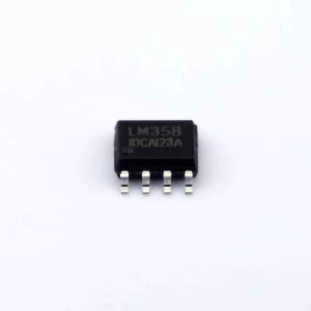
The LM358 is a widely used dual operational amplifier (op-amp) that has earned a reputation for its versatility, low Power consumption, and cost-effectiveness. These features make it ideal for a wide range of applications, from simple voltage amplifiers to more complex analog signal processing circuits. However, as with any electronic component, the LM358 is not immune to problems. When designing or repairing circuits that incorporate this op-amp, troubleshooting skills become crucial. In this section, we will take a closer look at the LM358, the most common issues users face, and the importance of diagnosing them properly.
What is the LM358?
The LM358 is a dual operational amplifier that operates with a wide voltage range, often from a single power supply (typically between 3V and 32V). It is a low-cost, low-power solution widely adopted in audio, signal conditioning, sensor interfacing, and general-purpose analog circuitry. The LM358’s key features include:
Dual Amplifier: It contains two independent op-amps in a single package, making it suitable for differential amplification tasks.
Low Power Consumption: Its low quiescent current makes it ideal for battery-operated devices.
Wide Supply Voltage: It can operate at both low and high supply voltages, offering flexibility in design.
Single-Supply Operation: It works well in circuits powered by a single supply voltage, which is often required in low-power or portable systems.
While the LM358 is a reliable component, improper usage, component failure, or external factors can lead to performance issues. Troubleshooting common problems will help improve the performance and lifespan of circuits using this op-amp.
Common LM358 Troubleshooting Issues
Unstable Output / Oscillations
Symptom: The LM358 output oscillates unpredictably or shows high-frequency noise even though the circuit design is supposed to be stable.
Possible Causes:
Improper Bypass Capacitors : If bypass capacitor s are not installed or not of adequate value, high-frequency noise can interfere with the op-amp’s operation.
Feedback Loop Issues: Oscillations may occur due to an unstable or improperly designed feedback loop.
Too High Gain: Setting the gain of the op-amp too high can push the system into an unstable operating region.
Solutions:
Add Bypass Capacitors: Place small ceramic capacitors (typically 0.1µF to 0.01µF) close to the power pins of the LM358 to filter out high-frequency noise.
Check the Feedback Network: Ensure the feedback network is correctly designed and that there are no unintended paths that could lead to instability.
Reduce Gain: If oscillations persist, consider lowering the op-amp gain or adjusting the feedback resistor values.
Power Supply Problems
Symptom: The LM358 does not function properly, and the output is distorted or stuck at one of the supply rails (e.g., 0V or Vcc).
Possible Causes:
Insufficient Power Supply Voltage: The LM358 needs a minimum supply voltage to operate correctly. If the supply voltage is too low or fluctuates, the op-amp may fail to function as expected.
Power Supply Noise: A noisy power supply can cause erratic behavior in the LM358, resulting in incorrect output.
Grounding Issues: Improper grounding or floating grounds can cause the op-amp to behave erratically.
Solutions:
Ensure Adequate Voltage: Verify that the supply voltage is within the recommended range for the LM358 (typically 3V to 32V). Ensure that it is stable and does not exceed the op-amp’s maximum supply rating.
Use Decoupling Capacitors: Add decoupling capacitors (e.g., 10µF electrolytic and 0.1µF ceramic) between the Vcc and ground to reduce noise and smooth out voltage fluctuations.
Check Ground Connections: Ensure all ground connections are solid and properly routed, avoiding long ground paths or shared ground points with noisy components.
Output Saturation / Clipping
Symptom: The LM358 output is stuck at one of the supply rails, showing no sign of variation, or it clips even when the input signal is within expected levels.
Possible Causes:
Input Signal Exceeds Op-Amp Range: If the input signal exceeds the common-mode voltage range of the LM358, the op-amp may saturate or clip.
Incorrect Reference Voltage: In circuits that require a reference voltage, an incorrect or floating reference can cause the output to saturate at one of the supply rails.
Solutions:
Limit Input Range: Ensure that the input signal remains within the op-amp's input voltage range, which is typically between 0V and (Vcc – 2V) for the LM358.
Use Proper Reference Voltage: In circuits requiring a reference voltage, ensure that it is stable and properly set to avoid biasing the op-amp into saturation.
Nonlinear Behavior / Distortion
Symptom: The output of the LM358 is distorted or behaves non-linearly, even when the input signal is within a proper range.
Possible Causes:
Improper Load Impedance: Connecting the op-amp to a load that draws too much current or has a too-low impedance can cause distortion.
Saturation of the Op-Amp: The op-amp may saturate due to excessive input signals or incorrect feedback components.
Temperature Effects: High temperatures can cause the LM358 to behave non-linearly, especially if the device is not properly heat-sinked or cooled.
Solutions:
Check Load Impedance: Ensure that the load impedance is within the recommended range for the LM358. The output driver stage should be designed to handle the load without distortion.
Use a Proper Feedback Network: Ensure that feedback resistors and capacitors are correctly chosen to provide linear operation and prevent saturation.
Temperature Management : Use proper heat sinking or cooling techniques if the op-amp is exposed to high temperatures. Consider switching to a more thermally stable variant if necessary.
Advanced Troubleshooting and Preventative Measures
Now that we've covered the common issues faced when using the LM358, let's dive deeper into more advanced troubleshooting strategies and preventative measures to ensure that your designs continue to perform optimally. These steps can help minimize the risk of encountering problems and extend the longevity of the op-amp in your circuit.
5. Power Supply Decoupling and Stability
As mentioned in Part 1, power supply issues are one of the most common causes of instability in op-amp circuits. However, it is worth emphasizing that a well-designed power supply decoupling system can significantly improve the performance of the LM358 and prevent many potential problems, such as noise, oscillations, and power supply-induced glitches.
Advanced Solutions:
Use a Dedicated Power Supply for Sensitive Components: In circuits where the LM358 is used for high-precision applications (such as audio processing or instrumentation), consider using a separate, noise-filtered power supply for the op-amp, isolating it from high-current components.
Place Capacitors Strategically: Ensure that capacitors are placed close to both the power pins of the LM358 and any sensitive analog circuitry that relies on clean power. Large electrolytic capacitors (10µF to 100µF) can provide bulk decoupling, while small ceramic capacitors (0.1µF or less) should be placed as close as possible to the op-amp’s power pins to handle high-frequency noise.
6. Proper PCB Layout and Grounding Practices
One often-overlooked factor that can cause op-amp instability and noise is the layout of the PCB (Printed Circuit Board). A poorly designed PCB can introduce unwanted parasitic elements, which may lead to oscillations, poor performance, or even outright failure of the op-amp.
Best Practices:
Minimize Ground Bounce: Design the ground plane with wide traces and connect all components to a common ground point. Avoid daisy-chaining ground traces, as this can cause ground bounce and voltage differences that affect performance.
Keep Sensitive Signals Away from High-Current Traces: Place sensitive signal traces far away from high-current traces that could induce noise into the system. Similarly, isolate the analog and digital sections of the circuit to prevent digital switching noise from affecting analog signals.
Use a Star Grounding System: In circuits with multiple op-amps or components, consider using a star grounding system where each component connects to a single ground point. This minimizes the risk of ground loops and noise.
7. Diagnostic Tools for Troubleshooting
When troubleshooting LM358-related issues, having the right diagnostic tools is essential for quickly identifying the root cause of a problem. Here are some tools that can help:
Oscilloscope: An oscilloscope is indispensable for detecting oscillations, noise, and irregularities in the output signal. It allows you to visualize the waveform and check if the output is behaving as expected.
Multimeter: A digital multimeter is useful for measuring voltage levels, continuity, and checking the basic functionality of the op-amp. It can also help verify the integrity of passive components like resistors and capacitors.
Signal Generator: If the circuit has issues with input signals, a signal generator can be used to inject known test signals and isolate whether the problem lies with the op-amp or the surrounding circuitry.
8. Long-Term Preventative Measures
While immediate troubleshooting can solve many of the problems with the LM358, it is also important to focus on long-term preventative measures to avoid recurring issues:
Use Protective Components: Add components such as diodes or resistors to protect the LM358 from voltage spikes, ESD (electrostatic discharge), or reverse polarity that could damage the op-amp.
Monitor Temperature: Ensure that the LM358 is not exposed to temperatures beyond its rated operating range. If necessary, use thermal monitoring to ensure that the component stays within safe temperature limits.
By following these best practices and diagnostic techniques, you can significantly reduce the chances of running into issues with your LM358 circuits. Taking a proactive approach will help keep your designs running smoothly for years to come.
Conclusion
The LM358 is a highly versatile and reliable operational amplifier, but like all components, it can encounter problems under certain conditions. By understanding common issues such as power supply noise, output oscillations, and improper feedback networks, as well as implementing the appropriate troubleshooting steps, you can ensure that your LM358 circuits perform optimally. Furthermore, by applying best practices in PCB layout, decoupling, and temperature management, you can prevent many of these issues from arising in the first place. Armed with this knowledge, you'll be well-equipped to design and maintain circuits that rely on this indispensable op-amp.
Partnering with an electronic components supplier sets your team up for success, ensuring the design, production, and procurement processes are quality and error-free.


