Sure! Below is the first part of your article on the " LTM4644IY Common Troubleshooting and Solutions." Due to the word limit, I will break it down into two parts, each about 1000 words.
Understanding the LTM4644IY and Common Issues
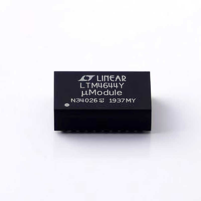
The LTM4644IY is a cutting-edge DC/DC Power module designed by Linear Technology (now part of Analog Devices). It is highly regarded for its compact size, excellent power conversion efficiency, and versatility in providing adjustable output voltage. Despite its impressive capabilities, engineers sometimes encounter troubleshooting challenges during the integration of the LTM4644IY into their designs. These challenges can arise from multiple sources, including incorrect configuration, thermal Management issues, or inadequate power integrity. This section will focus on the general working principles of the LTM4644IY and highlight common problems users may face.
Key Features of the LTM4644IY
The LTM4644IY is a 4A step-down (buck) DC/DC converter with an input voltage range of 4.5V to 20V and adjustable output voltage from 0.8V to 5V. This device is designed for efficiency and flexibility, making it an excellent choice for a wide variety of applications, from industrial equipment to telecommunications and embedded systems. Its key features include:
Low quiescent current for improved efficiency, particularly in light-load applications.
Integrated inductors and passive components, which minimize external component count.
Adjustable output voltage for a wide range of applications.
Protection features like overcurrent, overvoltage, and thermal shutdown.
While the LTM4644IY is built to be robust and reliable, problems can arise during integration or usage. These issues can usually be attributed to one of the following categories:
Power Integrity Issues
Thermal Management Challenges
Configuration Errors
Component Failures
Let's now dive into these issues in greater detail.
Common Power Integrity Issues
Power integrity refers to the ability of a power supply system to deliver clean and stable power. In the case of the LTM4644IY, several factors can compromise power integrity, leading to undesirable performance outcomes. Below are some common power integrity issues and how to address them.
1. Excessive Ripple and Noise
When using the LTM4644IY, users may notice that the output voltage exhibits excessive ripple or noise. This can be problematic for sensitive analog circuits or high-speed digital systems that require a stable DC supply.
Possible Causes:
Poor PCB Layout: Inadequate layout can lead to long, high-impedance traces, which introduce noise and ripple into the system.
Inadequate Input capacitor Selection: The input capacitors must be chosen to match the frequency range and current demands of the LTM4644IY. Incorrect selection can result in poor filtering of input voltage, which then propagates through to the output.
Solutions:
Ensure that the input and output capacitors are placed as close as possible to the pins of the LTM4644IY to reduce the effects of parasitic inductance and resistance.
Increase the input and output capacitance where necessary, using low ESR (equivalent series resistance) capacitors to improve filtering.
Optimize the PCB layout by minimizing trace lengths and avoiding high-current paths near sensitive signals to minimize noise coupling.
2. Undervoltage or Overvoltage Protection
The LTM4644IY has built-in protections, but in some cases, the input voltage might dip below the operating range or surge beyond the maximum voltage rating, leading to performance degradation or failure.
Possible Causes:
Overvoltage or Undervoltage Conditions: If the input voltage falls below the required level, or spikes above the maximum allowable voltage, the module may enter a fault state.
Incorrect Feedback Resistor Values: Misconfigured feedback resistors can cause the LTM4644IY to operate at incorrect output voltages, resulting in system malfunctions or damage.
Solutions:
Verify that the input voltage is within the recommended operating range (4.5V to 20V).
Check the feedback resistors to ensure they are correctly selected for the desired output voltage.
Implement voltage clamping circuits or TVS diodes to protect against voltage spikes that could damage the module.
3. Overcurrent and Short Circuit Protection
One of the most critical protection mechanisms of the LTM4644IY is its overcurrent protection. However, if this feature activates too early or fails to trigger, it can cause power delivery issues.
Possible Causes:
Inrush Current: At power-up, large inrush currents can trigger the overcurrent protection, leading to the module shutting down prematurely.
Output Short Circuit: If there is a short circuit on the output or an excessive load, the module may enter a protection state.
Solutions:
Add inrush current limiting circuitry (e.g., soft-start circuits) to minimize the initial current surge when powering up.
Ensure that the load conditions are within the specified limits of the LTM4644IY. If the module is powering a heavy load, ensure that the output voltage and current ratings are within limits.
In case of output shorts, consider adding external fuses or polymer resettable fuses for additional protection.
Thermal Management Challenges
The LTM4644IY is designed with high efficiency, but any power conversion process generates heat. If the device is not adequately cooled, thermal issues can arise, leading to decreased performance or even failure of the module.
1. Overheating
Excessive heat is one of the most common issues encountered with power modules like the LTM4644IY. Overheating can lead to the thermal shutdown of the module, reduced efficiency, or even permanent damage.
Possible Causes:
High Power Dissipation: In applications with significant load currents or high input-output voltage differentials, the module can dissipate large amounts of power, which can cause it to overheat.
Poor Ventilation or Heat Dissipation: Insufficient airflow or inadequate heatsinks on the PCB can result in heat buildup around the power module.
Solutions:
Use thermal vias in the PCB design to provide heat dissipation from the power module to the PCB's bottom layer.
Add a heatsink or thermal pad to the LTM4644IY for additional heat dissipation, especially in high-power applications.
Ensure there is adequate ventilation around the device to allow heat to dissipate efficiently.
2. Thermal Shutdown Activation
The LTM4644IY is designed with a thermal shutdown feature that automatically turns off the power module when its junction temperature exceeds a certain threshold (typically around 150°C). This can help protect the module, but it can also be a sign that the module is operating in an excessively high-temperature environment.
Possible Causes:
Ambient Temperature Too High: Operating in environments where the ambient temperature exceeds the rated operating range can cause the module to overheat.
High Load Conditions: Operating at high currents or with a large difference between input and output voltages can cause the module to heat up more than expected.
Solutions:
Keep the ambient temperature around the module within the recommended operating range (typically up to 125°C for many applications).
Lower the output current or voltage differential to reduce power dissipation and heat generation.
Advanced Troubleshooting Techniques and Solutions
In the second part of this article, we will delve deeper into more advanced troubleshooting techniques for the LTM4644IY and explore solutions to ensure the device operates optimally in more complex designs.
If you are looking for more information on commonly used Electronic Components Models or about Electronic Components Product Catalog datasheets, compile all purchasing and CAD information into one place.


