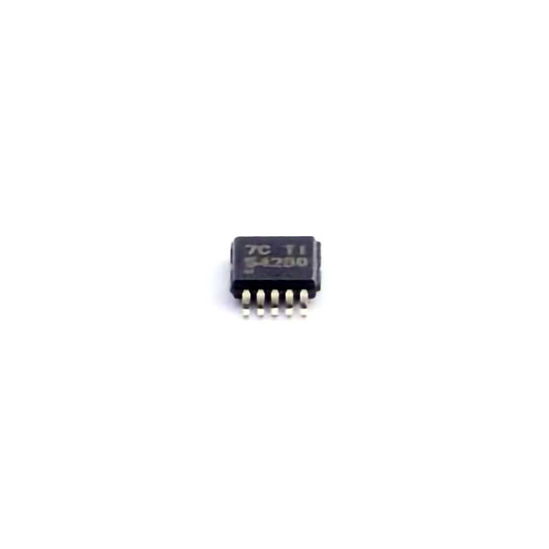
The TPS54260DGQR is a high-performance, efficient buck converter that provides reliable Power supply solutions for a variety of applications. However, as with any complex electronic component, users may encounter issues during integration or operation. This article provides a detailed guide to troubleshooting common issues with the TPS54260DGQR and offers practical solutions to ensure optimal performance.
TPS54260DGQR, troubleshooting, power supply, buck converter, voltage regulator, electronic components, power efficiency, power management IC, solution, repair, integration tips
Understanding the TPS54260DGQR and Common Issues
The TPS54260DGQR is a sophisticated, highly efficient buck converter designed by Texas Instruments to supply stable output voltage in various applications such as communications, industrial equipment, and automotive systems. This power management integrated circuit (PMIC) operates by stepping down a higher input voltage to a regulated output voltage. While it is a reliable and versatile component, it may present challenges for users, especially during the design or deployment stages. Understanding common issues and how to troubleshoot them is essential for smooth operation.
1.1 Overview of the TPS54260DGQR
Before diving into troubleshooting, it’s crucial to understand the functionality and key features of the TPS54260DGQR. It is a synchronous step-down regulator that operates with a wide input voltage range of 4.5V to 60V and provides an adjustable output voltage from 0.8V to 15V. This buck converter integrates several protective features, such as overcurrent protection, thermal shutdown, and undervoltage lockout (UVLO), making it an excellent choice for efficient power conversion.
Its efficiency, up to 96%, and its compact size make it suitable for applications requiring high efficiency in power conversion, such as:
Consumer electronics
Automotive systems
Industrial control systems
Medical devices
Despite its robust features, users may face challenges in correctly configuring the device or diagnosing performance issues. Some of the most common issues include voltage instability, excessive heat dissipation, or incorrect output voltage. Identifying the root cause of these issues is essential for smooth integration.
1.2 Common Troubleshooting Issues
Incorrect Output Voltage
One of the most common problems faced by users is incorrect output voltage. This may result from a variety of issues, such as incorrect feedback resistors, external components that do not meet the specifications, or incorrect operation of the feedback loop.
Solution:
Check Feedback Resistor Values: The TPS54260 uses a feedback mechanism to regulate its output voltage. Incorrect resistor values can cause a deviation in the output voltage. Ensure that the feedback resistors are chosen based on the desired output voltage as per the formula provided in the datasheet.
Inspect for External Components: Make sure that external components like capacitor s, inductors, and diodes are properly rated and correctly placed in the circuit. The inductor’s value should also be within the recommended range to avoid instability.
Check for Proper Grounding: An improper grounding system can cause significant errors in output voltage. Ensure that the ground connections are solid and without noise.
Overheating
Overheating is a potential concern for power converters. Excessive heat can lead to thermal shutdown or permanent damage to the IC and surrounding components. Overheating might also indicate that the power converter is underperforming or stressed.
Solution:
Optimize Heat Dissipation: Ensure that the TPS54260 has adequate PCB layout with a good heat sink and thermal vias to dissipate heat effectively. Utilize copper planes to distribute the heat across the board.
Reduce Load Current: Check whether the load on the power converter is too high for the regulator. Overloading the converter can cause it to overheat. Consider using a converter with a higher current rating if necessary.
Proper Component Selection: Ensure that the input capacitors and output capacitors have the correct voltage ratings and low equivalent series resistance (ESR) to minimize power loss and heat generation.
Noise and Ripple Issues
Noise and ripple on the output voltage are common problems that can affect the performance of sensitive circuits, such as those found in communications or audio applications. These issues are often due to improper capacitor selection or poor PCB layout design.
Solution:
Increase Output Capacitor Size: A larger output capacitor can help smooth out ripple and reduce noise. Use low ESR capacitors, which help to improve the overall performance of the power converter.
Check PCB Layout: Proper PCB layout is essential for minimizing noise. Ensure that the high-current paths are kept separate from the sensitive feedback and control lines. The ground plane should be continuous and solid, and traces should be as short as possible.
Add Filtering: Adding additional passive components such as ferrite beads or additional decoupling capacitors can help filter out noise and ripple from the output.
Under Voltage Lockout (UVLO) Issues
The TPS54260 has an undervoltage lockout (UVLO) feature, which ensures that the converter will not operate if the input voltage falls below a certain threshold. This feature helps prevent the converter from malfunctioning when the input voltage is unstable or too low to provide a stable output.
Solution:
Check Input Voltage Levels: Ensure that the input voltage is above the UVLO threshold. If the input voltage is too low, the converter will not operate properly. Make sure the input power source is stable and capable of supplying the required voltage.
Verify the UVLO Setting: The TPS54260 allows you to adjust the UVLO threshold through external resistors. Ensure that the resistors are correctly configured to set the proper UVLO threshold for your specific application.
Advanced Troubleshooting and Best Practices for the TPS54260DGQR
Now that we’ve covered some of the basic troubleshooting issues, let’s explore advanced techniques for diagnosing and resolving more complex problems. These solutions involve deeper insights into the IC’s behavior, performance monitoring, and some best practices for optimizing the design and deployment.
2.1 Analyzing Stability and Load Transients
Another issue commonly encountered is instability or oscillations in the output voltage, particularly when there are rapid changes in load current. This is often referred to as "load transient response" and can be attributed to improper component selection or poor feedback control.
Solution:
Stabilize with Proper Compensation: The TPS54260 requires compensation to ensure stability, particularly when operating with varying loads. Check the compensation network and make sure it is designed according to the recommendations in the datasheet.
Use a Properly Rated Inductor: The choice of inductor plays a significant role in the converter’s transient response. Ensure that the inductor has the right current rating and inductance value. A too-high inductance value can cause slow response times, while too low can cause instability.
Optimize Load Response: If rapid load changes are expected, increase the output capacitor size and use multiple capacitors with different values to improve the transient response.
2.2 Fault Conditions and Protection Features
The TPS54260 is equipped with a range of protective features to safeguard the IC and connected components. These include overcurrent protection (OCP), thermal shutdown, and soft-start mechanisms. If any of these protective mechanisms are triggered, the IC may stop functioning or enter a fault state.
Solution:
Check Overcurrent Protection (OCP): If the output current exceeds the specified limit, the IC will enter a fault condition. Use a current probe to check the actual load current and compare it with the converter’s current limit. If the current exceeds the limit, reduce the load or improve the cooling.
Check Thermal Shutdown: If the IC gets too hot, it will enter thermal shutdown to protect itself. Ensure that the PCB layout is optimized for heat dissipation. Use temperature sensors to monitor the temperature of the IC during operation.
Soft-Start Configuration: If the output voltage rises too quickly or too slowly during startup, it can lead to stability issues. Ensure the soft-start capacitor is correctly sized to limit the inrush current and allow for a smooth ramp-up of the output voltage.
2.3 Optimizing PCB Layout for Maximum Efficiency
A key aspect of troubleshooting involves examining the layout of your PCB. A poorly designed PCB can lead to a variety of issues such as excessive noise, instability, or poor heat dissipation.
Solution:
Minimize High-Current Paths: High-current traces should be kept as short and wide as possible to minimize resistance and reduce voltage drop. Place decoupling capacitors as close as possible to the IC to reduce noise and ripple.
Use Solid Ground Plane: A continuous, uninterrupted ground plane is essential for reducing noise and improving signal integrity. Avoid running sensitive signal traces over power planes to prevent interference.
Ensure Adequate Decoupling: Place ceramic capacitors close to the input and output pins of the TPS54260 to reduce high-frequency noise. The input capacitor helps stabilize the input voltage, while the output capacitor improves transient response and reduces ripple.
2.4 Monitoring and Debugging with Evaluation Tools
Texas Instruments provides a variety of evaluation tools and software to help troubleshoot and optimize the performance of the TPS54260. The use of these tools can significantly speed up the debugging process and provide valuable insights into the IC’s behavior.
Solution:
Use the TPS54x0EVM Evaluation Module: The TPS54x0EVM evaluation board is a great resource for quickly testing and evaluating the performance of the TPS54260. It allows you to monitor real-time data such as input/output voltages, current, and efficiency.
Use Simulation Software: Texas Instruments provides Power Designer software, which allows you to simulate the power conversion process, estimate component values, and verify performance under various load and voltage conditions.
Conclusion
The TPS54260DGQR is a powerful and efficient buck converter that can provide stable power to a wide range of applications. By understanding the common troubleshooting issues and implementing the right solutions, you can ensure that the device performs optimally in your designs. Proper configuration, component selection, and PCB layout are essential for avoiding common pitfalls, while advanced tools and techniques can help resolve more complex issues. With the knowledge of troubleshooting techniques provided in this guide, you can maximize the potential of the TPS54260 and ensure that your power conversion needs are met with reliability and efficiency.
If you are looking for more information on commonly used Electronic Components Models or about Electronic Components Product Catalog datasheets, compile all purchasing and CAD information into one place.


