Understanding the MCP3421A0T-E/CH and Its Common Issues
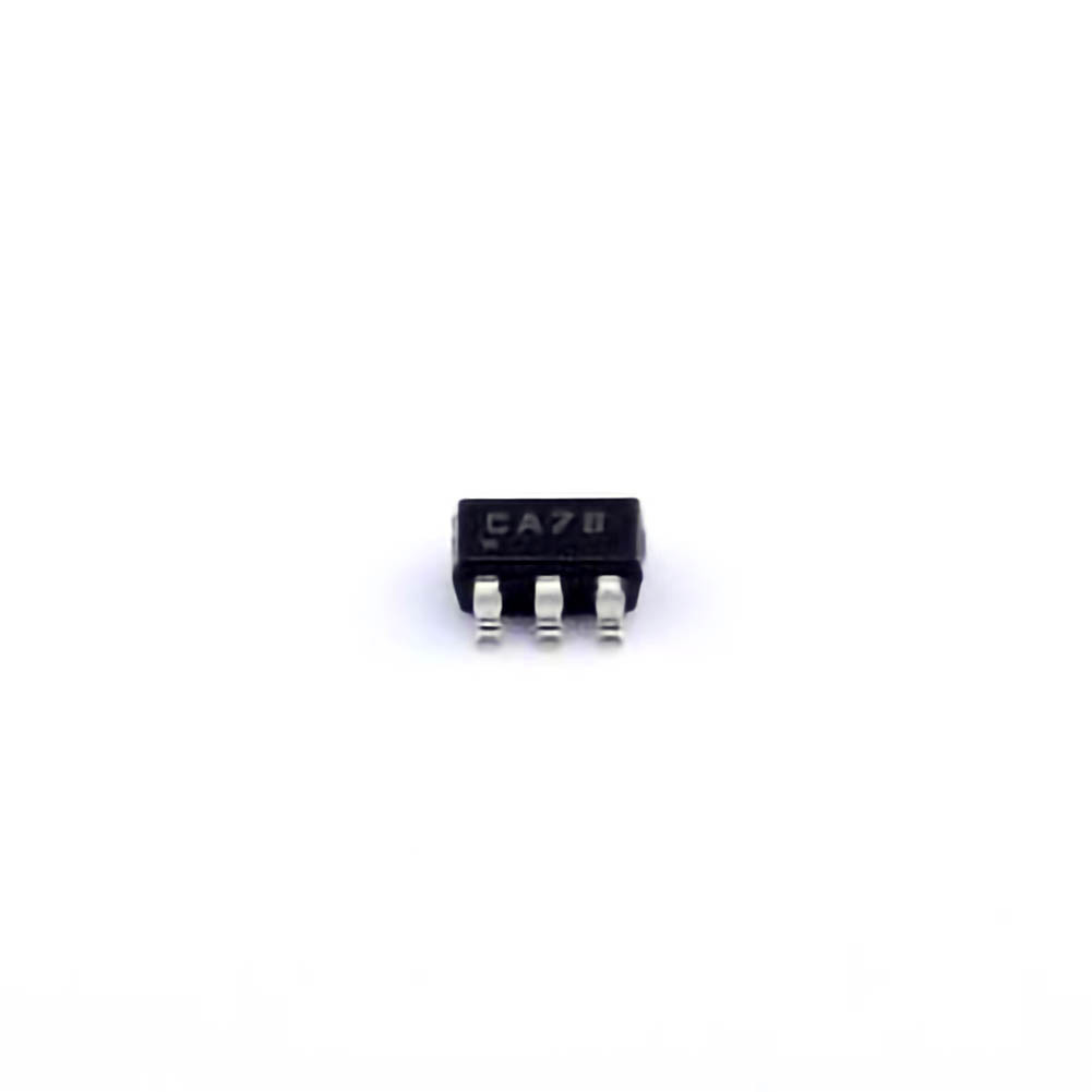
The MCP3421A0T-E/CH is a high-resolution, low- Power 18-bit ADC from Microchip Technology. It is widely used for a range of applications such as data acquisition, sensor interfacing, and precision measurement systems. The device offers high accuracy with a built-in programmable gain amplifier (PGA) and a differential input, making it ideal for precise, low-level analog signal conversion into a digital format.
Despite its advantages, users may encounter various issues while working with this component. In this first part of the article, we'll explore some of the most common problems faced by engineers and designers when integrating the MCP3421A0T-E/CH into their systems, along with initial troubleshooting steps to mitigate these issues.
1. Power Supply Issues
One of the most frequent problems encountered with the MCP3421A0T-E/CH is power supply-related. If the device is not receiving the correct voltage levels or has insufficient power, it may not operate correctly. The MCP3421A0T-E/CH requires a stable supply voltage within the range of 2.7V to 5.5V, typically derived from a regulated source.
Troubleshooting steps:
Verify the power supply voltage with a multimeter to ensure that it falls within the recommended range.
Check for noise or fluctuations in the power supply, which may affect the ADC's performance. Use an oscilloscope to detect any voltage ripple.
Ensure that the ground connections are solid, as poor grounding can introduce noise and cause erratic behavior.
2. Incorrect Reference Voltage
The MCP3421A0T-E/CH relies on an external reference voltage (Vref) to determine the input signal range. A mismatched or unstable Vref can lead to inaccurate measurements or Communication errors.
Troubleshooting steps:
Confirm that the Vref pin is connected to a stable, accurate reference voltage.
Ensure that the reference voltage is within the specified range for the device (typically 2.7V to 5.5V).
Use a voltage regulator or a precise reference IC to supply a stable Vref, especially in high-precision applications.
3. Faulty Communication
The MCP3421A0T-E/CH communicates with the microcontroller or processor through the I2C interface . Communication failures or improper configuration may prevent data from being correctly transmitted or received.
Troubleshooting steps:
Check the I2C bus connections (SCL, SDA, and ground) for continuity and ensure there are no shorts.
Ensure that the I2C address is correctly configured. The default address for the MCP3421A0T-E/CH is 0x68 for 7-bit addressing.
Verify that the microcontroller or processor is correctly initializing the communication and handling the protocol as expected.
Use a logic analyzer or oscilloscope to monitor the I2C signals to check for Timing issues or data corruption.
4. Low Accuracy or Noise Issues
Another common problem is poor accuracy in the ADC readings, which can be caused by noise, interference, or incorrect settings. The MCP3421A0T-E/CH offers high resolution and is capable of measuring small changes in input signals. However, it is also sensitive to noise, especially when used in high-precision applications.
Troubleshooting steps:
Implement proper decoupling capacitor s close to the Vdd and Vss pins to minimize power supply noise.
Consider using a low-pass filter on the input signal to reduce high-frequency noise.
Place the MCP3421A0T-E/CH on a well-grounded PCB with a solid ground plane to minimize electromagnetic interference ( EMI ).
Verify the Clock source for the device; an unstable or noisy clock can degrade the ADC’s accuracy.
5. Incorrect Configuration of Sampling Rate
The MCP3421A0T-E/CH allows users to configure the sampling rate of the ADC to optimize performance for different application needs. However, incorrect configuration of the sampling rate or oversampling can affect the measurement results.
Troubleshooting steps:
Ensure that the conversion rate is set according to the application’s requirements. The device offers multiple resolution and sampling rate options, including 18-bit resolution at a slower sampling rate or lower resolution with faster sampling.
Verify that the configuration register is set correctly to match the desired resolution and sampling rate.
Consider using a slower sampling rate when high precision is required, as faster rates can reduce resolution.
Advanced Troubleshooting and Solutions for Optimal Performance
In the first part of this article, we covered some of the more common and easily diagnosed issues when working with the MCP3421A0T-E/CH. In this section, we will dive deeper into more advanced troubleshooting strategies and solutions to ensure optimal performance, especially in complex or high-precision applications.
6. Temperature Sensitivity
Temperature variations can significantly impact the performance of the MCP3421A0T-E/CH. The accuracy of the ADC can drift with temperature changes, especially in environments with extreme temperature conditions.
Troubleshooting steps:
Ensure that the MCP3421A0T-E/CH is operating within its specified temperature range, typically -40°C to +85°C.
If the application involves wide temperature fluctuations, consider adding temperature compensation algorithms to account for ADC drift.
Use temperature-stable reference sources or integrate a temperature sensor to monitor and adjust for temperature-induced errors.
7. Input Impedance Mismatch
The MCP3421A0T-E/CH may experience inaccuracies if the impedance of the signal source is too high, as this can affect the device’s ability to accurately sample the input signal. High input impedance can cause signal attenuation or delays, leading to incorrect readings.
Troubleshooting steps:
Ensure that the input signal has a sufficiently low impedance (preferably less than 10kΩ for high-resolution measurements).
If needed, use a buffer op-amp with a low output impedance to drive the ADC input.
Use a signal conditioning circuit, such as a differential amplifier or PGA, to match the impedance of the signal source to the ADC.
8. Handling Differential Inputs
The MCP3421A0T-E/CH supports differential inputs, which means the input signal is measured between two different points. Incorrect wiring or grounding issues can result in erroneous readings, especially when dealing with small signal measurements.
Troubleshooting steps:
Verify that the differential input pins (INA and INB) are correctly wired and connected to the signal source.
Ensure that the signal source is differential in nature and that both input signals are within the common-mode voltage range.
Consider using differential signal amplifiers to boost the input signal before feeding it into the MCP3421A0T-E/CH.
9. Clock and Timing Issues
The MCP3421A0T-E/CH operates based on a clock that defines the timing of its conversion cycle. Any issues with the clock signal can result in conversion errors or unexpected behavior.
Troubleshooting steps:
Check the clock input for stability and ensure that it is within the recommended frequency range (typically 1MHz to 20MHz).
Use a low-jitter clock source for applications requiring precise timing.
If using an external crystal or resonator, check the component values and ensure that they match the device’s requirements.
10. Firmware or Software Configuration Errors
In many cases, issues with the MCP3421A0T-E/CH may not stem from hardware problems but from software or firmware misconfigurations. If the microcontroller is not properly interfacing with the ADC or interpreting the data incorrectly, it can lead to misleading results.
Troubleshooting steps:
Review the firmware code to ensure that the MCP3421A0T-E/CH is being initialized properly and that the correct register settings are applied.
Use an oscilloscope or logic analyzer to inspect the communication between the microcontroller and the MCP3421A0T-E/CH to ensure data is being transferred correctly.
Implement proper error-checking in the software to detect any issues with the conversion process, such as timeouts or incorrect results.
Conclusion: Maximizing Performance with MCP3421A0T-E/CH
The MCP3421A0T-E/CH is a versatile and reliable ADC, but like any electronic component, it requires careful attention to detail during design and operation. By understanding common troubleshooting techniques and solutions, engineers can ensure that the MCP3421A0T-E/CH performs optimally in their applications. From power supply stability to communication integrity, addressing these common issues can help avoid costly mistakes and improve overall system performance.
By applying the troubleshooting strategies outlined in this article, users can solve many of the common issues encountered with the MCP3421A0T-E/CH and ensure that their systems operate with high precision and reliability.
Partnering with an electronic components supplier sets your team up for success, ensuring the design, production, and procurement processes are quality and error-free.


