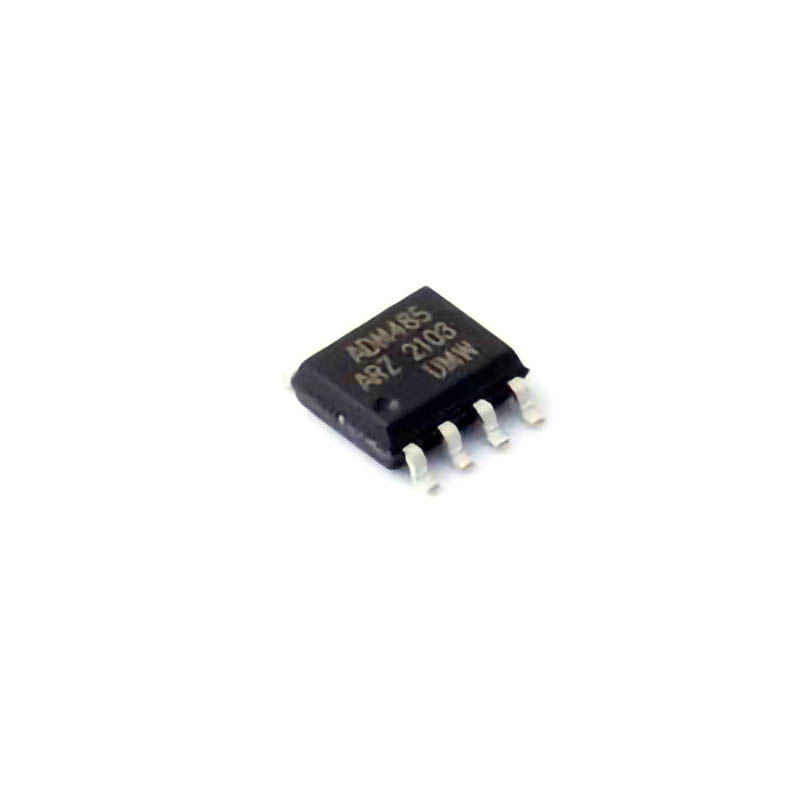
Identifying Common Issues with ADM485ARZ
The ADM485ARZ is a robust RS-485 transceiver that plays a pivotal role in industrial communication systems, such as factory automation, HVAC control, and other data transmission networks. While this component is known for its durability and high performance, users may still encounter common issues during its integration or operation. In this part, we will explore the primary issues faced with the ADM485ARZ, including signal degradation, improper wiring, and Power supply concerns.
1.1 Signal Degradation and Data Loss
One of the most frequent issues when working with the ADM485ARZ is signal degradation, which can lead to data loss or miscommunication. RS-485 systems often use differential signaling, where the voltage difference between two wires represents data. However, several factors can cause the signal quality to degrade:
Long Cable Runs: RS-485 systems are designed for long-distance communication, but excessive cable lengths—especially beyond 4000 feet (about 1200 meters)—can result in signal attenuation.
Poor Termination Resistance : Inadequate termination at both ends of the bus can result in reflections, causing data corruption or intermittent communication issues.
Excessive Bus Loading: The ADM485ARZ has a limited drive capability (typically 32 devices on a single bus), and exceeding this limit can lead to signal degradation and communication failures.
Solution:
To address signal degradation, ensure proper termination at both ends of the RS-485 bus. Use 120-ohm resistors at each end of the bus and avoid excessive cable lengths by using twisted-pair cables that are designed for RS-485 communication. Additionally, consider using Repeaters or signal boosters for longer distances. If too many devices are on the bus, consider adding additional repeaters or employing a star topology to reduce bus loading.
1.2 Incorrect Wiring or Configuration
Miswiring is a common cause of communication failure with the ADM485ARZ. RS-485 transceivers require proper differential pair wiring to operate correctly. Common wiring mistakes include:
Incorrect A and B Lines: In RS-485, it's essential to correctly identify the A and B lines. If these are swapped, communication will fail.
Incorrect Grounding: RS-485 systems require a solid ground connection between all devices. A floating ground or poor grounding can result in unreliable communication or damage to the components.
Improper Biasing: The ADM485ARZ features an automatic fail-safe biasing that ensures the A and B lines stay within acceptable voltage levels when no devices are transmitting. However, improper external biasing or floating lines can still cause issues.
Solution:
Double-check your wiring configuration, ensuring the A and B lines are connected correctly and that a common ground is established across all devices. Additionally, ensure that the fail-safe biasing feature is enabled or add external resistors as necessary for optimal operation.
1.3 Power Supply and Voltage Fluctuations
Power-related issues can also affect the ADM485ARZ's functionality. Fluctuations in voltage levels, noise, or inadequate power supply stability can cause erratic performance. The ADM485ARZ operates within a 3.3V to 5V supply range, but supply issues may lead to:
Low or Overvoltage: Insufficient or excessive voltage can cause unreliable performance or complete failure of the transceiver.
Power Supply Noise: If the power supply is noisy or lacks proper filtering, the ADM485ARZ may exhibit erratic behavior, such as random data drops or failure to transmit/receive properly.
Solution:
Use a regulated power supply that provides a stable voltage within the specified range. It's also advisable to incorporate capacitor s for filtering high-frequency noise and providing voltage stability. When designing the power supply, ensure proper decoupling capacitors are placed close to the power pins of the ADM485ARZ to minimize any noise interference.
1.4 Ground Loops and EMI
Electromagnetic interference (EMI) and ground loops can disrupt the operation of any high-speed communication component, including the ADM485ARZ. Industrial environments, in particular, can generate substantial EMI, which may corrupt data transmission.
Ground Loops: Ground loops occur when there are multiple ground paths with differing potentials, creating unwanted currents that interfere with the signal.
Electromagnetic Interference (EMI): High-frequency noise from motors, power lines, or other equipment can induce spikes or transients on the RS-485 lines.
Solution:
To mitigate ground loops, ensure all devices share a common ground point and avoid creating multiple ground paths. Additionally, use twisted-pair cables with shielded layers to reduce EMI. The shield should be grounded at only one end to prevent ground loops.
Solutions and Best Practices for Reliable ADM485ARZ Operation
While diagnosing and addressing the issues mentioned in Part 1 is crucial, it's equally important to implement best practices for reliable long-term operation of the ADM485ARZ. In this part, we'll explore how to optimize the design, perform effective testing, and ensure that your RS-485 network remains stable and efficient.
2.1 Ensuring Proper Termination and Biasing
Termination and biasing are essential elements in an RS-485 network. Without proper termination, reflections can occur, and without proper biasing, the differential voltage might not remain within the required range for reliable communication.
Termination: Each end of the RS-485 bus should have a 120-ohm resistor to match the characteristic impedance of the transmission line. This resistor ensures that the signal doesn't reflect back and cause data corruption.
Biasing: RS-485 requires a differential voltage between the A and B lines to determine the transmitted data. Without correct biasing, the lines may float, causing undefined states.
Best Practice:
Always include a 120-ohm termination resistor at each end of the bus. If you're working with short cable lengths or a low-data-rate system, you might be able to skip termination at the mid-point, but this should be carefully tested. Implement external biasing resistors if your system needs more stability or if you’re running into issues with the fail-safe biasing feature.
2.2 Using Proper Cable and Connectors
RS-485 communication quality is highly dependent on the choice of cable and connectors. Twisted-pair cables are preferred for their ability to cancel out electromagnetic interference and maintain signal integrity over long distances.
Twisted-Pair Cables: These cables are designed specifically for differential signaling and offer superior noise rejection. A twisted pair of wires for the A and B lines is ideal for preventing common-mode noise from corrupting the signal.
Shielding: In environments with high EMI, shielded twisted-pair (STP) cables should be used. The shield helps block external noise, ensuring that the differential signal remains clean.
Best Practice:
For high-speed or long-distance communication, always use twisted-pair cables and consider shielded variants in electrically noisy environments. Keep the cable lengths as short as possible and avoid running RS-485 cables in parallel with high-power lines.
2.3 Implementing Signal Repeaters for Extended Distance
As previously mentioned, RS-485 systems are designed for long-distance communication, but the signal may degrade over large distances or when many devices are connected. Using repeaters can significantly improve signal integrity and extend the communication range.
Repeaters: RS-485 repeaters amplify the signal and allow it to travel longer distances, supporting more devices along the bus.
Network Topology: Star topologies are often used in conjunction with repeaters, as they isolate different parts of the network, improving overall reliability.
Best Practice:
When planning a long-distance or large network, always consider using repeaters or isolators to extend the range. A star topology combined with repeaters can prevent too many devices from overloading a single bus and ensure better data integrity.
2.4 Monitoring and Testing for Early Fault Detection
Once the system is up and running, it's essential to monitor its performance continuously. Early fault detection can prevent larger system failures and minimize downtime. Regular testing and diagnostic tools can help identify potential problems before they become critical.
Oscilloscopes and Logic Analyzers: These tools allow you to monitor the differential signal in real-time, ensuring that the voltage levels are within the acceptable range and that the communication is occurring without errors.
Error Checking: Regularly check for communication errors, such as parity or framing errors, and address the root causes promptly.
Best Practice:
Implement regular testing procedures and use diagnostic tools to monitor the health of the RS-485 network. If possible, design your system with error-checking mechanisms in place, such as checksums or cyclic redundancy checks (CRC), to ensure data integrity.
2.5 Conclusion
The ADM485ARZ is an excellent choice for RS-485 communication, offering reliable performance in a variety of applications. By understanding common issues such as signal degradation, wiring problems, and power supply issues, and by implementing best practices like proper termination, biasing, and using suitable cables, you can ensure a smooth and reliable communication system. With careful planning, testing, and monitoring, your RS-485 network will deliver robust performance for years to come.
If you are looking for more information on commonly used Electronic Components Models or about Electronic Components Product Catalog datasheets, compile all purchasing and CAD information into one place.


