Introduction to MAX3232IPWR and Common Issues
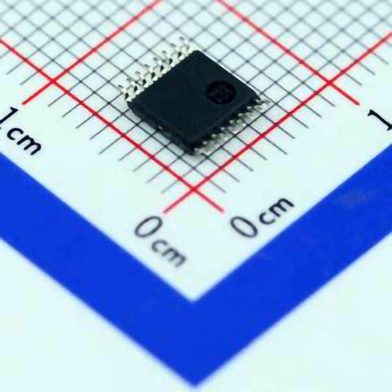
The MAX3232IPWR is a highly popular IC used for converting RS-232 serial Communication signals to TTL (Transistor-Transistor Logic) signals and vice versa. It is widely employed in embedded systems, industrial applications, and microcontroller projects due to its reliability and ease of integration. This IC enables communication between devices that operate on different voltage levels, such as microcontrollers, PCs, sensors, and other serial devices.
However, like any component, the MAX3232IPWR can encounter issues during operation. Understanding the most common problems and how to troubleshoot them effectively is crucial for ensuring a smooth and efficient communication setup. In this article, we will cover typical issues you may face while working with the MAX3232IPWR and provide practical solutions for resolving them.
Common Problems When Using MAX3232IPWR
Signal Integrity Issues
One of the most frequent problems when using the MAX3232IPWR is poor signal integrity. Since the MAX3232IPWR operates with high-speed signals, it’s vulnerable to noise, signal degradation, and interference. When this happens, communication between devices can become unreliable, leading to data corruption, lost packets, or inconsistent transmission speeds.
Incorrect Voltage Levels
The MAX3232IPWR is designed to convert voltage levels from RS-232 (±12V) to TTL (0V to 5V). If the voltage levels on either side of the converter are incorrect, the IC may fail to operate properly. This can be caused by improper connections, faulty wiring, or using incompatible voltage levels for your specific devices.
Insufficient Power Supply
Like any IC, the MAX3232IPWR requires a stable and sufficient power supply for proper operation. Insufficient or unstable power can lead to erratic behavior, such as unreliable data transmission, system resets, or failure to initialize. Ensuring that your circuit is powered correctly is key to avoiding these problems.
Incompatible Baud Rates
Baud rate mismatches between the MAX3232IPWR and the devices communicating over the RS-232 interface are another common issue. The baud rate determines the speed at which data is transmitted between devices. If the baud rates don’t match, data transfer errors or complete communication failure can occur.
Wrong Pin Connections
Incorrectly connecting the pins of the MAX3232IPWR can result in improper communication. Many users overlook the pinout diagram or misinterpret which pins are for transmission (TX), reception (RX), and ground (GND), leading to a non-functional setup.
How to Identify and Fix These Issues
In this section, we will delve deeper into how to troubleshoot these issues and find suitable solutions. Let’s go through each of the common problems and discuss ways to address them.
1. Troubleshooting Signal Integrity
Signal integrity issues can manifest as data corruption or unstable communication between devices. Here’s how to deal with them:
Check for Noise: Ensure that the RS-232 and TTL lines are routed away from noisy power supplies, motors, or high-speed digital signals. Using shielded cables and proper grounding can significantly reduce noise and interference.
Use capacitor s: Placing small capacitors (typically in the range of 100nF) across the power supply pins (VCC and GND) of the MAX3232IPWR can help stabilize the voltage and reduce power noise.
Signal Termination: In cases where long cables or high-frequency signals are involved, consider adding termination resistors to the lines. This prevents signal reflection and ensures signal integrity is maintained over longer distances.
2. Voltage Level Issues
Ensuring that the voltage levels are within specification is essential for the MAX3232IPWR to function correctly:
Measure Voltage Levels: Use a multimeter or oscilloscope to verify that the RS-232 signal levels are in the range of ±12V, and the TTL side signals are between 0V and 5V.
Check for Voltage Clamping: Some devices may have built-in voltage clamping or protection circuitry that could limit or alter the expected voltage levels. Ensure that the connected devices are compatible with the MAX3232IPWR's voltage requirements.
3. Power Supply Issues
A common culprit behind unstable communication is an insufficient power supply. Here’s what you can do:
Verify Voltage: Ensure that the MAX3232IPWR is being powered by a stable 3.3V or 5V supply, depending on your specific setup. A power supply that fluctuates or falls below the required level can cause inconsistent behavior.
Check for Ground Loops: Make sure that the ground (GND) of the MAX3232IPWR is properly connected to the ground of all devices in the circuit. A floating ground or ground loop can introduce noise and cause communication failures.
4. Mismatched Baud Rates
Baud rate mismatches can lead to corrupted or garbled data. Here’s how to fix it:
Check Configuration: Verify that both the transmitting and receiving devices are set to the same baud rate. This configuration is typically done in the software or firmware of the microcontroller or computer terminal software.
Test with Known Baud Rates: If you're unsure about the baud rate configuration, try using standard baud rates such as 9600, 19200, or 115200, which are commonly supported by many devices.
5. Pinout and Wiring Errors
Wiring errors are often overlooked, but they can render your setup completely non-functional. Follow these steps to avoid common mistakes:
Double-Check Pinout: Before starting, always refer to the datasheet for the MAX3232IPWR and confirm the pinout. Incorrect wiring of TX, RX, and GND can prevent communication.
Check for Short Circuits: Inspect your wiring to ensure that there are no accidental short circuits or poor solder joints that might be interrupting the signal flow.
Advanced Troubleshooting and Tips for Ensuring Reliable Communication
After addressing the most common issues, let’s dive into some more advanced troubleshooting techniques and offer tips for maintaining a reliable communication setup using the MAX3232IPWR.
Advanced Troubleshooting Techniques
Oscilloscope Analysis
One of the best tools for diagnosing communication problems is an oscilloscope. By analyzing the signal waveform on both the RS-232 and TTL lines, you can gain insights into whether the signals are being transmitted correctly.
Check Waveform Integrity: Ensure that the waveforms resemble the expected square waves for TTL logic (0V and 5V) and the expected voltage levels for RS-232 (±12V). Distorted or noisy waveforms may indicate issues with grounding or power supply.
Measure Timing and Edges: Check for timing problems, such as jitter or improper edge transitions, which can point to issues with the baud rate or signal integrity.
Using Loopback Tests
A loopback test is an excellent way to verify that the MAX3232IPWR is functioning properly. To perform a loopback test:
Short TX and RX Pins: Connect the TX pin to the RX pin on the MAX3232IPWR.
Send Data: Send a known pattern of data from your microcontroller or terminal software and verify that the data is received correctly on the RX pin.
This test helps isolate issues to the MAX3232IPWR itself and confirm whether the communication setup is correct.
Isolation and Buffers
For complex or long-distance communication setups, consider using isolation techniques or buffer amplifiers to improve signal strength and protect devices from potential electrical damage.
Use Opto- Isolators : If you're working in an electrically noisy environment, opto-isolators can help protect the MAX3232IPWR and prevent ground loops by isolating the signal paths.
Buffer Signals: In cases where signal degradation is an issue, especially over long distances, adding buffer amplifiers can strengthen the signal and ensure reliable communication.
Best Practices for Maximizing Reliability
Use Quality Cables
Ensure that you use high-quality cables for both RS-232 and TTL connections. Low-quality or overly long cables can introduce noise and cause data transmission errors.
Temperature Considerations
The MAX3232IPWR, like all ICs, has operating temperature limitations. Ensure that your system operates within the recommended temperature range (typically -40°C to +85°C). High temperatures can lead to degraded performance or permanent damage to the IC.
Firmware and Software Updates
Make sure that your firmware or software configurations are updated and that they are compatible with the MAX3232IPWR's communication protocols. Regular updates ensure that you benefit from the latest bug fixes and performance enhancements.
Testing Under Load
Test the communication under the expected load conditions (e.g., maximum baud rate, full data transfer) to ensure that the MAX3232IPWR can handle the real-world operating conditions without failure.
Conclusion
Troubleshooting issues with the MAX3232IPWR can be daunting, but by methodically diagnosing and resolving common problems such as signal integrity issues, voltage mismatches, power supply problems, baud rate mismatches, and incorrect wiring, you can achieve stable and reliable communication in your system. By following the tips and techniques outlined in this article, you’ll be equipped to overcome any challenges and optimize your use of this powerful IC.
Partnering with an electronic components supplier sets your team up for success, ensuring the design, production, and procurement processes are quality and error-free.


