Understanding the LIS3DHTR Accelerometer and Common Issues
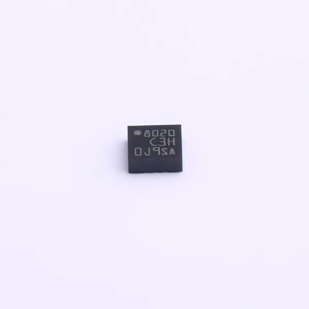
The LIS3DHTR is a high-performance, low- Power 3-axis accelerometer manufactured by STMicroelectronics. With its compact design and robust capabilities, it has found widespread use in a variety of applications, ranging from industrial automation to consumer electronics and wearable devices. However, like any electronic Sensor , users may encounter common issues when working with the LIS3DHTR, from sensor calibration to data Communication errors. In this first part of our comprehensive troubleshooting guide, we will explore the basics of the LIS3DHTR and address some of the most common problems users face.
1. Understanding the LIS3DHTR Accelerometer
The LIS3DHTR is a versatile sensor designed to measure acceleration along the X, Y, and Z axes, with a range of ±2g, ±4g, ±8g, and ±16g, depending on the configuration. It also features integrated temperature sensing capabilities, making it a valuable tool for precise motion sensing and orientation detection. The accelerometer communicates with external microcontrollers via I2C or SPI interface s, allowing it to seamlessly integrate with a variety of systems.
Despite its impressive capabilities, the LIS3DHTR is not immune to common issues that users may encounter when deploying or integrating it into their projects. These issues can range from power supply problems to incorrect sensor readings, communication failures, or failure to initialize the sensor properly.
2. Common Troubleshooting Issues with LIS3DHTR
Here, we will discuss several of the most common problems encountered by users when working with the LIS3DHTR accelerometer and offer practical solutions for each.
2.1 Problem: No Output or Sensor Not Responding
Cause: A lack of output or non-responsiveness from the LIS3DHTR sensor is often due to improper initialization or incorrect wiring.
Solution:
Check the Wiring: Verify that the sensor is correctly connected to the microcontroller or development board. Ensure that the power supply (VCC) is connected to the appropriate pin (usually 3.3V or 5V), and the ground (GND) is properly connected.
Ensure Proper Power Supply: The LIS3DHTR requires a stable voltage for proper operation. If the voltage is too high or too low, the sensor may not function correctly. Confirm that the voltage levels are within the recommended operating range (2.4V to 3.6V).
Initialize the Sensor Properly: When using the I2C or SPI interface, ensure that the initialization sequence is followed correctly. This involves setting the correct registers for data acquisition and enabling the appropriate output channels.
2.2 Problem: Inaccurate or Erratic Readings
Cause: Inaccurate readings or erratic sensor data may be caused by various factors, such as poor calibration, electromagnetic interference ( EMI ), or incorrect settings.
Solution:
Calibrate the Sensor: The LIS3DHTR requires proper calibration to ensure accurate measurements. If the sensor is providing inaccurate readings, perform a calibration procedure. The sensor may need to be calibrated for offset and gain to ensure correct readings in your application.
Reduce Electromagnetic Interference (EMI): High-frequency noise and electromagnetic interference can distort the sensor’s output. To mitigate this, use proper grounding techniques, shield the sensor, and place it in a low-EMI environment if possible.
Check the Sampling Rate and Sensitivity: Ensure that the sensor’s sampling rate and sensitivity are set to appropriate levels for your application. High sampling rates or overly sensitive settings can lead to noisy or inaccurate readings.
2.3 Problem: Communication Errors (I2C/SPI)
Cause: Communication issues between the LIS3DHTR and the microcontroller are often caused by incorrect wiring, incorrect communication protocol configuration, or faulty code.
Solution:
Verify the Communication Protocol: Ensure that the correct communication protocol (I2C or SPI) is selected and configured. If using I2C, check the addresses and make sure there are no address conflicts. For SPI, verify the clock polarity, clock phase, and the correct chip select pin.
Check Connections: Verify that the SDA (data) and SCL (clock) pins for I2C or MISO, MOSI, and SCK pins for SPI are correctly connected between the microcontroller and the LIS3DHTR sensor. Ensure that there are no loose connections, and that pull-up resistors are used where necessary (for I2C).
Monitor the Bus: Use a logic analyzer or oscilloscope to monitor the data transmission on the communication bus. This can help diagnose issues such as clock mismatches, missing bits, or incorrect timing.
2.4 Problem: Sensor Not Powering Up
Cause: If the LIS3DHTR is not powering up, it may be due to an issue with the power supply or incorrect wiring.
Solution:
Verify Power Supply Voltage: Double-check the power supply voltage to ensure it falls within the recommended range for the LIS3DHTR (typically 2.4V to 3.6V). If the voltage is too high or too low, the sensor will fail to power up.
Inspect the Power Rails: Ensure that the power supply rails are stable and that there are no short circuits or open connections. Use a multimeter to measure the voltage at the VCC pin and GND pin.
Test with Known Good Power Source: If possible, replace the current power source with a known, stable power supply to rule out issues with the original source.
2.5 Problem: High Power Consumption
Cause: High power consumption can result from the sensor operating at maximum resolution, high output data rates, or the continuous operation of additional features (such as the temperature sensor).
Solution:
Adjust Output Data Rate: The LIS3DHTR allows you to configure the output data rate (ODR). If power consumption is an issue, reduce the ODR to a lower value. A lower data rate will reduce the frequency at which the sensor updates the measurements, thereby saving power.
Turn Off Unnecessary Features: If you are not using the temperature sensor or certain axes, consider turning off those features to reduce power consumption.
Use Low-Power Modes: The LIS3DHTR offers several low-power modes that allow the sensor to operate in a reduced power state when full performance is not required. Consider using these modes to extend battery life in battery-operated applications.
Advanced Troubleshooting and Maintenance Tips for the LIS3DHTR
In the second part of this troubleshooting guide, we will delve deeper into advanced issues that may arise with the LIS3DHTR accelerometer and discuss strategies for diagnosing and resolving them. Whether you're dealing with complex sensor behaviors, intermittent failures, or need to ensure long-term reliability, this section will provide you with the tools and knowledge to tackle these challenges head-on.
3. Advanced Troubleshooting Techniques
3.1 Problem: Sensor Output Freezes or Stops Updating
Cause: This problem is often associated with incorrect sensor configurations, or it may indicate issues with the power supply or microcontroller communication.
Solution:
Check the Sensor Register Settings: In some cases, the sensor may freeze due to improper register settings. Recheck the sensor configuration, ensuring that the relevant registers for data output are properly configured and that the sensor is in an active mode.
Monitor for Interrupts or Warnings: The LIS3DHTR can generate interrupts based on specific thresholds or conditions (such as data overflows). Check if there are any interrupts configured that could be preventing the sensor from updating or if any warning flags are set.
Reset the Sensor: If the output freezes or the sensor stops responding, a reset may be required. This can often resolve communication glitches. Use the RESET pin or software reset to reinitialize the sensor and restore normal operation.
3.2 Problem: Drift in Accelerometer Readings
Cause: Sensor drift can occur over time, particularly when the sensor is exposed to temperature fluctuations, aging components, or external vibrations.
Solution:
Perform a Recalibration: If you observe drift in the sensor’s readings, consider recalibrating the accelerometer periodically. This is particularly important for applications that require high precision, such as robotics or industrial automation.
Compensate for Temperature Variations: The LIS3DHTR features a temperature sensor that can be used to compensate for temperature-induced drift. Monitor the temperature and apply corrections to the accelerometer data as needed.
Use Filtering Techniques: Software filtering algorithms (e.g., Kalman filtering) can help smooth out noisy data and reduce the impact of sensor drift on your measurements.
3.3 Problem: Sensor Sensitivity to External Vibrations
Cause: External vibrations, mechanical stress, or shock events can affect the performance of the LIS3DHTR, causing erroneous readings or sensor damage.
Solution:
Use Vibration Dampening Materials: To minimize the impact of external vibrations, consider using dampening materials such as rubber mounts or foam enclosures. This can help isolate the sensor from environmental vibrations.
Position the Sensor Carefully: Avoid mounting the sensor on locations where it will experience excessive mechanical stress or vibrations. The sensor’s accuracy can be compromised if subjected to external forces beyond its specified range.
Implement Software filters : Use digital filters to remove high-frequency noise caused by vibrations. A low-pass filter can help smooth out the data and reduce the effect of transient disturbances.
4. Long-Term Maintenance and Best Practices
4.1 Regular Calibration and Testing
To maintain accurate performance over time, it is essential to regularly calibrate the LIS3DHTR sensor, especially if the device is used in critical applications. Depending on the environmental conditions, you may need to perform calibration periodically to compensate for sensor drift, temperature changes, or mechanical wear.
4.2 Environmental Considerations
Ensure that the LIS3DHTR sensor is used within its specified operating conditions. Protect the sensor from extreme temperatures, humidity, or corrosive environments that could cause long-term damage or sensor degradation. If the sensor is used in an outdoor or industrial setting, consider using protective enclosures to shield it from harsh conditions.
Conclusion
The LIS3DHTR is an outstanding sensor, but like all electronic components, it requires careful handling and troubleshooting to ensure optimal performance. By following the strategies outlined in this guide, users can resolve common issues and ensure the accelerometer delivers accurate and reliable data. Proper initialization, calibration, and regular maintenance are key to keeping the sensor functioning at its best. Whether you're working on a simple consumer device or a complex industrial application, these troubleshooting tips and solutions will help you get the most out of the LIS3DHTR accelerometer.
Partnering with an electronic components supplier sets your team up for success, ensuring the design, production, and procurement processes are quality and error-free.


