Common Issues and Initial Troubleshooting
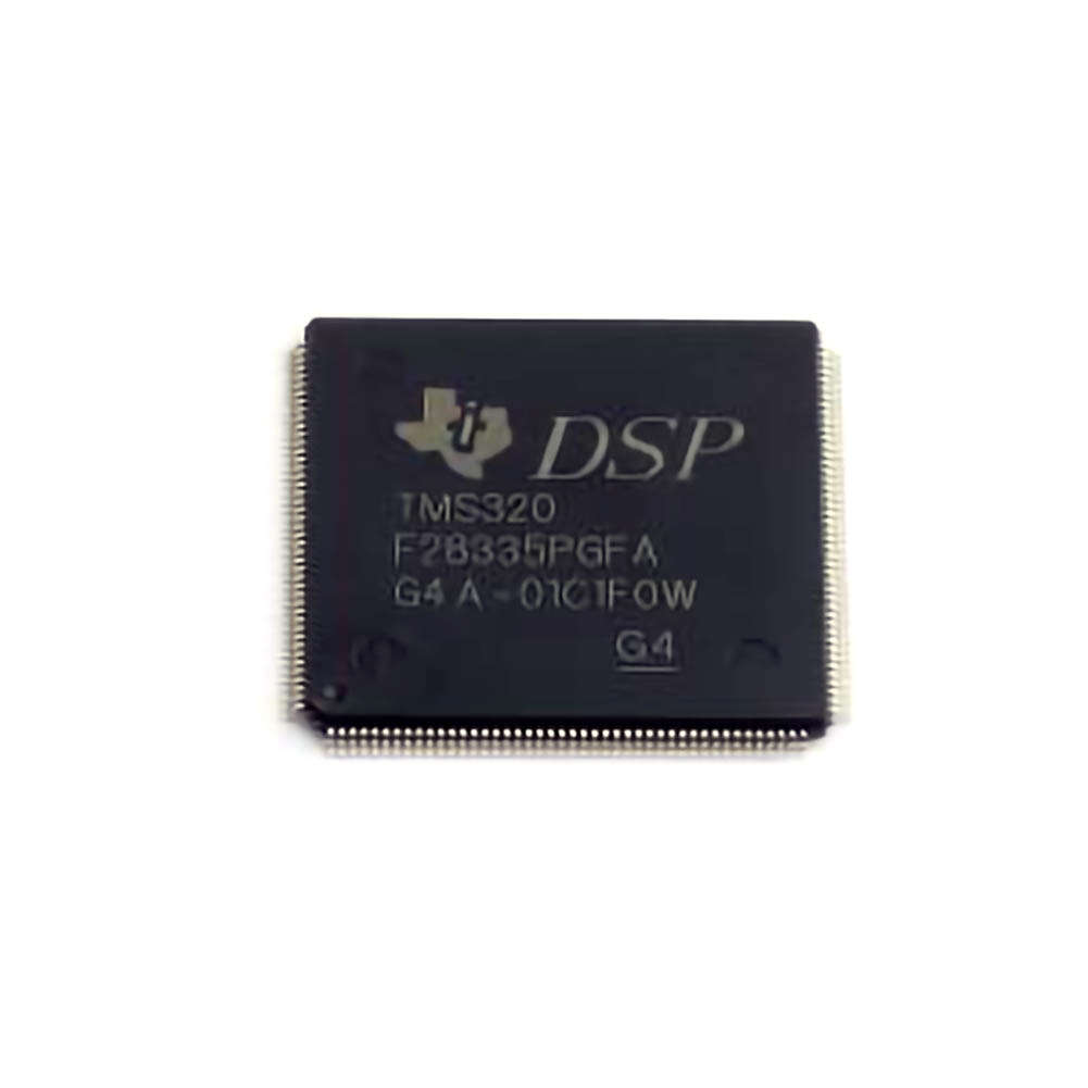
The TMS320F28335PGFA microcontroller, part of the C2000 family from Texas Instruments, is well-regarded for its high-performance capabilities in real-time control applications. These applications span across various industries, including automotive, industrial automation, renewable energy, and Communication s. However, like any embedded system, developers may encounter challenges during the design, development, and deployment phases. In this first part of our two-part series, we will focus on the most common issues users face when working with the TMS320F28335PGFA and provide initial troubleshooting steps to address them.
1. Power Supply Issues
A common issue faced when working with the TMS320F28335PGFA is improper power supply. This microcontroller has specific power requirements that must be met for proper operation. If the power supply is unstable or incorrectly configured, the microcontroller may exhibit erratic behavior, fail to start, or even get damaged.
Troubleshooting Power Supply Issues:
Verify Voltage Levels: Ensure that the voltage supplied to the microcontroller is within the recommended range. For the TMS320F28335PGFA, the core supply voltage (Vdd) should be 3.3V, and other peripheral voltages (e.g., I/O pins) may require different levels.
Check Ground Connections: A floating or poor ground connection can cause noise and instability. Ensure that all ground pins are properly connected to a stable ground plane.
Power-Up Sequence: Ensure that the power-up sequence adheres to the specifications in the datasheet. For instance, the core supply should be stable before any peripherals are powered up.
Measure Current Draw: Using an ammeter, check the current drawn by the device during startup. An excessively high current could indicate a short circuit or malfunction in the power supply or the microcontroller itself.
2. Inadequate Reset Functionality
The TMS320F28335PGFA includes a hardware watchdog timer and a system reset circuit to ensure proper initialization. However, failure to properly configure or trigger the reset function can lead to system instability or failure to boot up.
Troubleshooting Reset Functionality:
Check the External Reset Circuit: If you're using an external reset circuit, ensure that it is functioning correctly. A simple external reset circuit may include a push-button or a reset IC that generates a reset pulse to the microcontroller.
Monitor Reset Pin (XRSn): Use an oscilloscope to check the signal on the reset pin (XRSn) to ensure it is being triggered at the appropriate times. A stuck low or high state could prevent the microcontroller from resetting correctly.
Software Reset: The TMS320F28335PGFA allows for a software reset through specific registers. If the microcontroller enters an unknown state, issuing a software reset may help bring it back to normal operation.
3. Communication Problems (UART, SPI, I2C)
Interfacing with external devices via communication protocols like UART, SPI, or I2C is one of the primary tasks for many applications of the TMS320F28335PGFA. However, communication problems are common, especially when the system is first being set up.
Troubleshooting Communication Issues:
Signal Integrity: Use an oscilloscope to check the integrity of the signal on the communication lines. Poor signal quality, noise, or reflection may cause data corruption.
Protocol Configuration: Double-check the configuration settings for UART, SPI, or I2C peripherals. Incorrect baud rates, Clock polarities, or word lengths may result in miscommunication.
Pin Configuration: Ensure that the relevant I/O pins are correctly configured as inputs or outputs, depending on the interface . For example, the TX pin for UART should be set as an output, and the RX pin as an input.
Use Loopback Test: For serial communication, you can test the UART interface using a loopback test, where the transmitted signal is looped back to the receiver. This helps isolate the issue to the microcontroller or external device.
4. Clocking Issues
The TMS320F28335PGFA relies on an external crystal oscillator or clock source for its Timing . Problems with the clocking system can lead to failures in execution or inconsistent performance.
Troubleshooting Clocking Issues:
Check the Clock Source: Ensure that the external clock source is stable and configured correctly. If you're using an external crystal, verify that the resonant frequency and load capacitance match the specifications of the crystal.
Use the Internal Oscillator: If you're uncertain about the external clock, switch to the internal oscillator as a fallback to verify that the microcontroller itself is working properly.
Monitor Clock Pins: Use an oscilloscope to monitor the output of the clock pins. If you see a signal that is not within the expected frequency or waveform, you may have a problem with the clock source or its configuration.
5. Memory Issues
Memory problems can manifest as crashes, data corruption, or erratic behavior. The TMS320F28335PGFA has flash memory, RAM, and peripheral registers that must all be correctly managed.
Troubleshooting Memory Issues:
Check Memory Initialization: Ensure that the memory blocks are correctly initialized in your startup code. Uninitialized memory can lead to unpredictable behavior.
Test Memory with Diagnostic Tools: Use memory testing tools or simple code that writes and reads back values to verify that the memory is functioning correctly.
Inspect Bootloader Code: If your application includes a bootloader, ensure that it correctly loads code into the flash memory. A corrupt bootloader may prevent your application from running.
Advanced Troubleshooting and Debugging Strategies
In this second part, we will delve into more advanced troubleshooting techniques, including debugging strategies and resolving more complex issues that may arise when working with the TMS320F28335PGFA.
6. Interrupt Handling Problems
Interrupts are a critical part of the TMS320F28335PGFA’s real-time control functionality. Problems with interrupt handling can lead to missed events, inconsistent timing, or system crashes.
Troubleshooting Interrupt Handling:
Verify Interrupt Vector Table: Ensure that the interrupt vector table is correctly configured. Any misconfiguration can cause the microcontroller to jump to invalid or undefined addresses.
Check Interrupt Priorities: Review the priority of each interrupt and ensure that higher-priority interrupts are not being blocked by lower-priority ones.
Enable/Disable Interrupts Properly: Ensure that global interrupts are enabled before any interrupts are processed. Use __interrupt() attributes correctly when writing interrupt service routines (ISRs).
Use Debugger: Utilize a debugger to step through interrupt service routines and verify that interrupts are being triggered and handled as expected.
7. Peripheral Configuration Issues
In addition to communication peripherals like UART, SPI, and I2C, the TMS320F28335PGFA also has a wide range of other peripherals, such as ADCs, timers, and PWM outputs. Incorrect configuration of these peripherals can lead to functional failures in your application.
Troubleshooting Peripheral Configuration:
Check Peripherals Registers: Use a debugger or monitoring tool to check the configuration registers for each peripheral. Verify that the settings match the intended operation.
Enable Clock for Peripherals: Many peripherals in the TMS320F28335PGFA require the corresponding clock to be enabled. Check the clock gating configuration and make sure that the necessary peripheral clocks are active.
Verify Timing Requirements: For peripherals that require precise timing, such as PWM or ADC, ensure that the timing parameters are set correctly. Use an oscilloscope to measure signals and verify correct behavior.
8. Watchdog Timer Issues
The watchdog timer is a crucial component for system stability, ensuring that the system recovers from software crashes or hangs. However, improper configuration or failure to service the watchdog can lead to unintended resets.
Troubleshooting Watchdog Timer Issues:
Check Watchdog Timeout: Ensure that the watchdog timer’s timeout period is appropriately configured. If the timeout is too short, the system may be reset prematurely.
Servicing the Watchdog: Ensure that the watchdog timer is periodically serviced (reset) in the application code. Failure to do so will trigger a reset.
Use a Hardware Debugger: Use a hardware debugger to check the watchdog status and whether it is being triggered during normal operation.
9. Firmware/Software Bugs
Software bugs are often the hardest to identify, but they can have a significant impact on the performance and reliability of the system. The TMS320F28335PGFA’s complex architecture requires careful software design to avoid bugs.
Troubleshooting Software Bugs:
Use Debugging Tools: The TMS320F28335PGFA supports various debugging tools, such as JTAG and Code Composer Studio. Utilize these tools to set breakpoints, watch variables, and step through code.
Check for Buffer Overflows: Ensure that memory buffers are properly managed, especially when dealing with large data structures or communication buffers.
Review Compiler Optimization Settings: Some issues may arise due to aggressive compiler optimizations. Try disabling certain optimizations to identify potential issues caused by the compiler.
10. Environmental Factors
Finally, external factors such as temperature, electromagnetic interference ( EMI ), or physical damage to the microcontroller can contribute to problems.
Troubleshooting Environmental Issues:
Monitor Temperature: Ensure that the microcontroller is operating within its recommended temperature range. Overheating can cause instability.
Check for EMI: If you're working in an industrial or automotive environment, EMI can disrupt the microcontroller's operation. Use proper shielding and grounding techniques to minimize EMI.
Inspect Physical Damage: Check for visible signs of damage, such as burnt components, broken pins, or faulty solder joints.
Conclusion
By systematically addressing common power, reset, communication, memory, interrupt, and peripheral issues, engineers can resolve most challenges encountered with the TMS320F28335PGFA. Advanced debugging tools and techniques, combined with careful attention to environmental factors, will further enhance the reliability and performance of applications built around this powerful microcontroller.
If you are looking for more information on commonly used Electronic Components Models or about Electronic Components Product Catalog datasheets, compile all purchasing and CAD information into one place.


